This Stamping Die Design Fundamentals and Examples of Automotive Stampings article guide us to understanding the fundamentals of die stamping. And examples of automotive stamping parts production.
Definition of mold in the stamping die design fundamentals
Mold is a kind of industrial product that can be made in a certain way to shape the material in a specific structural form, and it is also a production tool that can produce industrial product parts with certain shape and size requirements in batches.
What are the mold types?
Molds include stamping, injection, hot pressing, foam, hot forging, and rubber molds.
What are the mold types of stamping dies?
Stamping dies include forming dies and repairing dies. Forming die includes stretching die, flanging dies, and shaping die. Trimming dies to include punching dies and trimming dies.
The following are the definitions of the different types of stamping dies.
Stretching die:
It is the most important equipment to ensure the production of qualified cover parts, and its function is to make the flat wool material into the main space workpiece by stretching process.
Trimming dies:
It is used to cut out the supplementary part of the process and the excess part of the pressure material flange of the drawn parts, and prepare the conditions for flanging and shaping, and it can be replaced by hand or other simple equipment in small batch production, and the trimming die is often used for punching.
Punching dies:
Punching die for separating scrap along the closed contour to get a perforated part on the blank or plate.
Flanging dies:
It is a part of the semi-finished workpiece that is turned over with respect to another part of the material.
Shaping die:
A die that adjusts the dimensional contour of a semi-finished product to improve dimensional accuracy and surface finish.
The characteristics of stamping die in the stamping die design fundamentals
What is stamping?
Stamping is a forming process in which a press and a die apply an external force to plates, strips, pipes, and profiles to produce a plastic deformation or separation to obtain a workpiece (stamping) of the desired shape and size.
What is the stamping part?
The metal or non-metal sheet is put into the die at room temperature, and the press and the die mounted on the press exert pressure on the sheet to separate or deform the sheet to make the desired part. This kind of part is called the stamping part.
Stamping classification in the stamping die design fundamentals
Cold stamping:
The metal processing at room temperature, generally the thickness of the plate <4mm;
Hot stamping:
The stamping processing method heats up the metal to a certain temperature range, and the plate thickness is 8~10mm or more.
Stamping characteristics in the stamping die design fundamentals
Less waste for complex parts;
Fine, smooth, and good interchangeability;
High rigidity and material saving;
Easy to control, high efficiency;
Low cost for mass production.
Materials for stamping in the stamping die design fundamentals
Mainly hot-rolled and cold-rolled steel plates and strips.
Commonly used low carbon steel, stainless steel, high plasticity alloy steel, copper, magnesium, aluminum and its alloy and other metal materials;
Non-metallic materials such as gumwood, mica, fiberboard leather, etc. are also widely used for stamping.
Mechanical properties of materials in the stamping die design fundamentals
(1) Plasticity
Plasticity refers to the ability of a solid material to deform permanently under the action of an external force without destroying its integrity.
(2) Strength
The ability of a metallic material to resist permanent deformation or fracture under static load
(3) Hardness
The ability of the surface of a metal material to resist being pressed into it by an object harder than it is
(4) Toughness
The ability of a metallic material to resist impact loading without being damaged
(5) Fatigue strength
The resistance of material parts and structural parts to fatigue damage
Stamping and forming properties of materials in the stamping die design fundamentals
Yield strength:
Yield strength refers to the maximum stress value of the metal when the yielding phenomenon occurs
Yield strength ratio:
The ratio of yield point (yield strength) to the tensile strength of steel, is called the yield strength ratio.
Elongation:
The percentage of elongation of a test bar from its original length when the metal material is broken by an external force (tensile force)
Hardening index and modulus of elasticity:
Hardening index n refers to the degree of hardening of the metal during cold deformation
The modulus of elasticity E refers to the ratio of positive stress to positive strain in the elastic deformation phase of a metal material.
Forming characteristics of various types of stamping dies in the stamping die design fundamentals
Stretching die:
Stretching the flat blank on the press to get curved hollow parts or covered parts.
Trimming die:
The flat, hollow, or three-dimensional solid parts will be cut off the excess outer edge.
Punching die:
The material inside the part is separated by a closed profile so that the part gets a hole.
Flanging die:
Stretching to form a flange on the edge of the original punched hole.
Shaping die:
The original bending or stretching parts through the mold pressed into the required shape.
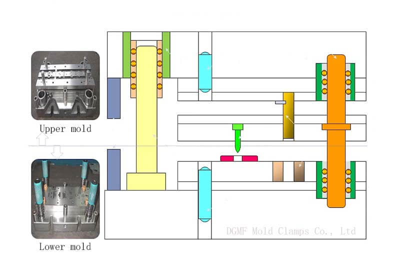
Structural composition of stamping die in the stamping die design fundamentals
According to the role and requirements of each part, the stamping die is mainly composed of two categories: process parts and structural parts.
Stamping die process parts
The parts that directly complete the stamping process, i.e. the parts that have direct contact with the material or the stamped parts. Such as forming parts (convex die, concave die), positioning parts (orientation plate, positioning pin), pressing parts (pressing circle), etc.
Stamping die structural parts
In the mold, it plays a role in the installation, combination, and guide parts. Such as support parts (upper and lower mold seat, convex and concave mold fixed plate), guide parts (guide pin, guide bush), fastening parts, etc.
Generally speaking, the automotive mold structure mainly includes the following parts.
Upper die, holder, lower die holder, press ring, convex die part, concave die part, various types of inserts, various types of diagonal cage hangers, orientation plates, positioning pins, orientation guide pillar guide bushings, limit devices, safety devices, stop plates, scrap slots, and various standard parts, etc.
Stamping process analysis and die production estimation in the stamping die design fundamentals
When accepting the commission of mold manufacturing, firstly, we should do the stamping process analysis according to the product parts drawing or the real object, analyze and study the number of sets of molds to be used, the mold structure, and the main processing methods, and then make the mold estimation.
Stamping process analysis in the stamping die design fundamentals
The stamping process is a processing method to obtain a certain size, shape, and performance of the workpiece by applying an external force to the blank through the die to produce plastic deformation or separation.
The stamping process has a wide range of applications. Since the processing is usually carried out at room temperature, it can process both metal sheets and bars, as well as a variety of non-metallic materials.
Stamping process analysis is the comprehensive determination of the best stamping process through all aspects of parameters.
The processability of the stamped part is directly related to the quality and cost of the product. A good stamping process is simple and easy to process, which saves raw materials and extends the service life of the tooling. At the same time, the product quality is stable.
Under the condition of production volume, the parts can be manufactured with high quality and low cost, and the production efficiency can be very good. When considering the processability of the stamped parts, the following principles should be followed in general.
(1) Simplify the production process as much as possible, consider the least and simplest stamping process to complete the whole part processing, and improve labor productivity.
(2) Ensure the stability of product quality and reduce the scrap rate.
(3) Simplify the die structure as much as possible to prolong the service life of the die.
(4) To improve the utilization rate of metal materials and reduce the variety of materials used.
(5) Conducive to the generality and interchangeability of products.
(6) The design of the parts should be convenient for stamping operation and conducive to mechanization and automation of production.
Stamping die estimation in the stamping die design fundamentals
(1) Tooling cost
It refers to material cost, purchased parts cost, design cost, processing cost, assembly adjustment, and trial mold cost. If necessary, also estimate the various processing methods used: tools and their processing costs, etc., and finally, arrive at the mold manufacturing price.
(2) Delivery time
Estimate the time to complete each job and decide the delivery period.
(3) Total life of the mold
estimating the single life of the mold and the total life of the mold after several simple repairs (i.e., the natural life of the mold without accidents).
(4) Product material
The performance, size, consumption, and utilization rate of the materials used for the product.
(5) The equipment used
Understand the performance and specifications of the equipment used in the application of the mold and its ancillary equipment.
Stamping die design in the stamping die design fundamentals
When carrying out stamping die design, first of all, we should try to collect as much information as possible and study it carefully before carrying out the stamping die design. If not, even if the designed mold has excellent function and high precision, it cannot meet the requirements, and the completed design is not the best design.
The information to be collected is as the below.
1). Information from the business side is most important and includes
Production volume (monthly and total production, etc.).
The unit price of the product.
Tooling prices and delivery periods.
The nature of the material to be processed and the method of supply, etc.
Future market changes, etc.
2). The quality requirements of the products to be processed, their use, and the possibility of design corrections, changes in shape, and tolerances.
3). Information on the production sector, including the performance, specifications, operating methods, and technical conditions of the equipment using the tooling.
4). Information about the mold manufacturing department, including processing equipment and technical level, etc.
5). The supply of standard parts and other outsourced parts, etc.
Classification of stamping dies in the stamping die design fundamentals
A stamping die according to the structure can be divided into single engineering die, composite die, and continuous die three categories.
The first two categories require more manpower does not match the economic efficiency, continuous die can be produced in large quantities with high efficiency. Similarly, the design of a set of high-speed precision continuous punching die, but also to the products you produce (including all products processed with stamping).
The design of a continuous punching die needs to pay attention to the spacing between each die set, parts processing accuracy, grouping accuracy, matching accuracy, and interference problems, in order to achieve the purpose of continuous die automation mass production.
The concept of stamping die unitized design in the stamping die design fundamentals
The stamping die overall structure can be divided into two major parts: the common part, according to the product, and the change the part. Common parts can be standardized or standardized, according to the product, and change in the part is difficult to standardize.
The composition of the template and specifications in the stamping die design fundamentals
1. The composition of the template
The composition of the stamping die will depend on the type and composition of the die and the difference, there are two major categories of configuration type structure and inverse configuration type structure. The former is the most commonly used structure, the latter structure is mainly used for drawing forming mold or with special mold.
The main tasks performed include.
(1) Digital mapping – the three-dimensional product and mold models into two-dimensional engineering drawings used in conventional processing.
(2) Digital design of the mold – according to the product model and design intent, establish the relevant three-dimensional solid model of the mold.
(3) Digital analysis and simulation of the mold – structural analysis of mold parts, thermal analysis, fatigue analysis, and motion analysis of the mold according to the product forming process conditions.
(4) Simulation of product forming process – injection molding, stamping, and forming.
(5) Customization of standard parts and standard design process suitable for our mold design.
(6) Mold production management.
2. Specifications of molds
(1) Mold size and locking screw
The size of the template should be larger than the working area and choose the standard template size. The position configuration of the clamping screw of the mold plate is related to the mold type and the size of the mold plate.
The single project mold most often uses the locking screw configuration in the four corners, the most standard form of the work area can be used in general. Long-shaped mold and continuous mold most often use the locking screw configuration in the four corners and the middle position.
(2) The thickness of the template
The selection of the thickness of the die plate is absolutely related to the structure of the die, the type of stamping process, the stamping process force, and the precision of the stamping process.
Based on theoretical calculations determining the thickness of the mold is difficult, generally, from experience, the design of the thickness of the template should be used as little as possible, with the height of the mold and clamping height to standardize to facilitate procurement and inventory management.
The design of the template in the stamping die design fundamentals
The main template of the continuous mold has a punch fixed plate, pressure plate, mother template, etc. Its structure design is according to the precision of the stamping products, production quantity, mold processing equipment, and processing methods, mold maintenance methods, there are three forms: block type, yoke type, and insert type.
Block type
The whole block-type template is also called one piece shape, and its processing shape must be closed. The whole block type template is mainly used in the simple structure or not high precision mold, its processing method is mainly cutting processing (without heat treatment), using heat treatment of the template must then implement wire cutting processing or electrical discharge processing and grinding processing.
Two or more pieces of one-piece type will be used for the occasion of long mold plate size (continuous mold).
Yoke type
The central part of the yoke-type template is machined into a groove to assemble the block. The structure depends on the application requirements, the groove part can be formed by another template.
The advantages of this yoke-type formwork structure are: easy processing of the groove, adjustable width of the groove, good processing accuracy, etc.; however, low rigidity is its disadvantage.
The design considerations of yoke-type formwork are as follows.
(1) The yoke plate and the block part of the embedding adopt the middle fit or light fit, if the strong pressure fit is adopted, the yoke plate will be changed.
(2) The yoke plate also has the function of holding the block parts, so it must be rigid enough to bear the side and surface pressure of the block parts. If the corner of the groove part of the yoke plate cannot be made into a clearance process, the block part must be made into a clearance process.
(3) The division of the block part should also consider its internal shape and the datum must be clearly defined. In order not to produce deformation when stamping, the shape of each block part should also be paid attention to.
(4) When the yoke plate is assembled with many block parts, the accumulated error in the processing of each block part will cause the pitch to change.
(5) The block parts adopt the die structure of a side-by-side combination because the block parts will bear the side pressure during the punching process to make the gap between the block parts or cause the block parts to be tilted. This phenomenon is an important reason for bad stamping size, chip blocking, and other bad stampings, so there must be adequate countermeasures.
(6) Depending on the size and shape of the block parts in the yoke plate, there are the following five methods of fixing: fixed by locking screws, fixed by keys, fixed by shaped keys, fixed by shoulders, and fixed by pressing parts (such as guide plates).
Inset type
This type of template is called inserted structure. The accumulated tolerance of this structure is small, has high rigidity, and good reproducibility of accuracy when decomposition and assembly.
Because of the advantages of easy mechanical processing, processing accuracy is determined by the working machine, and the final adjustment is less, the inserted template structure has become the mainstream of precision stamping dies, but its disadvantage is that it requires high precision hole processing machine.
When this template structure is adopted for continuous stamping dies, the empty station is designed to make the template have high rigidity requirements. The precautions of the inserted template structure are as follows.
(1) The processing of embedded holes.
The template embedded hole processing using a vertical milling machine (or jig milling machine) integrated processing machine, jig boring machine, jig grinding machine, wire-cutting discharge machine, etc. When using the wire-cutting and electrical discharge machine for the processing reference of the embedded holes, the wire-cutting process is carried out twice or more to improve processing accuracy.
(2) Fixing method of embedded parts.
The deciding factors of the fixing method of embedded parts are not to change the accuracy of its processing, the ease of assembling and disassembling, and the possibility of adjustment.
Embedded parts of the following four fixed methods: fixed by screws, fixed by the shoulder, fixed by the toe block, and the upper part of the plate to press.
The method of fixing the embedded parts of the mother template is also used to press into the fit, which should avoid the result of relaxation due to the thermal expansion of the process, and should be designed to prevent rotation when processing irregular holes using a round mold sleeve embedded parts.
(3) Considerations of insert assembly and decomposition.
Inserts and their cavities are processed with high accuracy to be assembled.
In order to get even a slight dimensional error that can be adjusted when assembling, it is advisable to consider in advance to solve the countermeasures, the specific considerations of the embedded parts processing are the following five items.
There is a press-in part to adjust the press-in state and correct position of the insert with a spacer, and there is a hole for press-out on the bottom of the insert, and the same size of the screw should be used for locking and loosening when locking with a screw.
Design of stamping die unitization in the stamping die design fundamentals
Die alignment unit
The die alignment unit is also known as the die edge parts of the alignment guide device. In order to maintain the alignment of the upper and lower die and shorten its preparation time, according to the product precision and production quantity, and other requirements, the die alignment unit mainly has the following five kinds:
- No guide type:
The die installed in the punching machine directly to its edge parts of the cooperation, without using the guide device.
- External guide type:
This device is the most standard structure, the guide device is installed in the upper die base and lower die base, not through each template, generally known as the die base type.
- External guide and internal guide type (a):
This device is the most commonly used structure for continuous dies, and the internal guide is installed between the punch fixing plate and the press plate. The punch and the mother die are aligned using the fixing pin and the external guide. Another function of the internal guide is to prevent the plate from tilting and to protect the small punches.
- External guide and internal guide type (2):
This type of device is the structure of high precision high speed continuous die, the internal guide device through the punch fixing plate, press plate, mother die fixing plate, and so on. The inner guide device itself also has the die edge parts to close and protect the role of a small punch. The main function of the outer guide is to decompose and install the die in the punching machine to get a smooth purpose.
- Inner guide type:
This structure does not use the outer guide device, the inner guide device through the punch fixing plate, pressure plate, and mother die fixing plate, etc., to correctly maintain the position of each plate relationship to protect the punch.
Guidance and guide unit
There are two types of guide and guide units in the mold: external guide type (mold base type or called the main guide) and internal guide type (or called the auxiliary guide). Another line with the requirements of precision mold is the use of external guidance and internal guidance and the high demand for the type.
(1) external guide type:
Generally, it is used in the die does not require high precision, mostly with the die base constituting a unit of trafficking, the main role is the die installed in the punching machine when the edge of the parts together, with almost no dynamic precision maintenance effect in the stamping process.
(2) internal guide type:
Because of the progress of the mold processing machine, recently been popularized rapidly. In addition to the main role of the die installed in the punching machine, the edge of the parts together, but also has the dynamic accuracy of the stamping process to maintain the effect.
(3) external guide and internal guide with type:
A pair of dies at the same time use an external guide and internal guide device.
Punch and mother die unit (round)
(1) Punch unit:
According to its shape (shoulder type and flat type), length, and convenience of maintenance, it is appropriate to use the punch unit in conjunction with the press plate guide unit.
(2) concave die unit:
Round concave die unit is also called mother die guide unit, the form of the whole block type and separate type, according to the production quantity, service life, and the handling of products or chips, the combination of the mother die unit series are using the template to directly process the shape of the mother die, with two beveled gap section, whether to use the back plate, irregular mother die shape must have a rotary prevention design.
Pressing bolt and spring unit
(1) Pressing bolt unit:
The types of pressboard bolts are external screw type, sleeve type, and internal screw type. In order to keep the press plate parallel to the specified position, the stopping method of the press bolt (shoulder contact part): die holder cavity bearing surface, punch fixed plate top surface, punch back plate top surface.
(2) Press spring unit:
The movable press plate press spring unit can be roughly divided into the following types: stand-alone type and the type used with press bolt.
When choosing a press spring unit, it is best to consider the following points before deciding.
Ensuring the free length of the spring and the necessary compression (springs with high compression should be placed in the recess of the platen).
The need for initial spring compression (pre-compression) or load adjustment.
Consider the ease of die set-up or maintenance.
Consideration of the relationship with the length of the punch or press bolt.
Consider the safety (to prevent the spring from flying out when it breaks).
Guiding pin unit (positioning of material feeding direction)
(1) Guide pin unit:
The main function of the guide pin is to obtain the correct feeding pitch during the continuous stamping process. The guide unit for stamping dies has two forms: indirect type (guide pin alone) and direct type (guide pin is installed inside the punch).
(2) The guide pin is assembled in the same way as the punching head (mounted on the punch fixing plate). The spring is used to restrain it to the punch-fixing plate.
(3) The guide pin is additionally mounted on the press plate. Since it is required that the guide pin protrudes from the press plate by a certain amount and prevents it from easily carrying the processed material when the die rises, it is necessary to pay attention to the rigidity of the press plate and the form of guidance.
(4) The guide pin unit has a direct type, which is installed in the punch, mainly used for shape punching (down processing) or the cutting edge processing of the lead project, and its position is positioned using the hole of the product and the inner diameter of the lead part.
Guide unit
(1) The guiding unit is used for profile punching (down feed processing) or continuous stamping processing in order to guide the width direction of the material to be processed and to obtain the correct feed pitch.
(2) The guiding device in the direction of the width of the strip is guided by: fixed plate guiding pin type, movable guiding pin type, plate tunnel guiding type (single plate), plate guiding type (two pieces), rising pin guiding type (movable, fixed or both).
(3) Start-stop guide device, its form: slider type, movable pin type and so on two, the main role is the initial starting position of the material placed in the mold positioning.
(4) Feeding stop device, which can correctly determine the feeding pitch, mainly used for manual feeding occasions, in the form of a fixed stop pin, movable stop pin, edge cutting stopping method, hook stop mechanism, or automatic stop mechanism.
(5) Side-pushing guide mechanism, when the material is pressed to one side during the stamping process, it can prevent the snaking phenomenon caused by the difference between the width of the material strip and the width of the guide.
(6) Positioning guiding mechanism of an embryo, its forms are fixed pin guiding type (using the shape of an embryo); fixed pin guiding type (using the hole of an embryo); guiding plate (for large parts); guiding plate (one body shape); guiding plate (split shape).
Lifting and top material unit
(1) Lifting pin unit
Its main function is to lift the material strip to the mother die when continuous stamping processing is carried out (the height of the position is called the feeding height and the purpose of smooth feeding is achieved; its forms are as below.
(round, purely for lifting the material), the most common type of lifting pin unit.
Lifting pin type (round, with holes for guide pins), the lifting pin has holes for guide pins to prevent the material from being deformed by the guide pins and to make the guide pins really work.
This is the most common type of lift pin type used for continuous mold guiding.
The lift pin type (square) is equipped with an air blow hole if required.
Lifting and guiding pin type (square).
(2) Top material unit
The automatic stamping process must prevent the punching products or chips from jumping on the surface of the mother die to avoid damage to the die and the generation of bad stamping parts.
(3) Ejector unit
The main function of the ejector unit is to eject the products or scrap from the mother die during each stamping process. The ejector unit is installed in two places: the reverse-configuration die set in the upper part of the die; the smooth-configuration die set in the lower part of the die.
Fixed pin unit
Fixed pin unit shape and size according to the standard specifications and design, the use of precautions are.
A fixed pinhole should be through the hole, can not be the occasion, consider it easy to use the design method of screw removal.
The length of the fixed pin should be moderate, not greater than the necessary length.
The pinhole should have the necessary escape part.
In the case where the upper part of the die is placed, a fall prevention mechanism should be designed to prevent it from falling; in the case where one side is pressed in and the other side is sliding, the hole of the sliding side should be slightly larger than the fixed pin.
The number of fixed pins should be two, and the same size should be chosen as much as possible.
Pressing plate unit
The press plate unit is especially important because the press surface and the mother die surface has the correct parallelism and buffer pressure requirement balance.
Failure detection unit
When stamping with a continuous die, the die must be designed to detect the error detection unit to detect whether the change in the feed pitch exceeds its benchmark and stop the operation of the punching machine.
A failure detection unit is installed in the mold, according to its detection method there are two installation forms as follows.
The upper die is equipped with a detector pin, which will detect when it deviates from the hole of the bar and will contact the bar.
The lower die is equipped with a checkout pin, which is detected when a part of the strip comes into contact with the checkout pin. Recently, the detection method using the contact method will be changed, and the number of cases of using proximity switches is increasing.
However, it is difficult to achieve complete error prevention because the detection is made near the lower dead center and there is a time difference between the start of detection and the stop of the punching machine.
The checkout device installed in the lower die can check out the material directly after the material feeding action is completed.
Scrap-cutting unit
During when continuous stamping process, the strips (scrap) will leave the mold one after another, and there are two ways to deal with it: using the coiling machine to pick it up, or using the mold-cutting device to cut it down.
And the latter way there are two: the use of special scrap cutting machine (set outside the stamping machine); installed in the continuous die cut-off unit of the final project.
Height stop block unit
The main function of the height stop block unit is to correctly determine the position of the dead point under the upper die, which has the following two forms: the way of frequent contact during the stamping process; the way of contact only during the assembly and no contact during the stamping process.
In order to prevent contact between the upper and lower die, it is better to put a spacer between the upper and lower die when the die is transported and stored. When precision is not necessary, the standard of use can be adjusted by screws.
Design of stamping dies main mold components in the stamping die design fundamentals
Standard parts and specifications
The best way to choose the standard specifications for the mold is to consider the following matters:
When the content of the specifications used is not limited, it is best to use the highest layer;
In principle, the standard number is used;
When the standard parts of the mold do not have this size, the closest one is used and then processed.
The design of the punch
Punch according to its function can be roughly divided into three major parts.
The apex of the edge of the processed material (cutting edge, the shape of irregular, square, round, etc.).
The contact part with the fixed plate of the punch (fixed part or shank, with irregular, square, or round cross-sectional shape, etc.).
The link between the cutting edge and the shank (middle part).
The design criteria for each part of the punch are briefly described in terms of the cutting edge length, the grinding direction of the cutting edge, the fixing method of the punch, and the shape of the shank.
(1) Cutting edge length
The design of the cutting edge length of the stage-type punch should take into consideration that no lateral bending will occur during processing, and the clearance with the moving part of the plate should be appropriate. The relationship between the press plate and the cutting edge of the punch is guided and unguided, and the length of the straight section of the cutting edge will be different.
(2) Grinding direction of cutting edge
The grinding direction of the cutting edge can be parallel to the shaft (up-cutting process) or perpendicular to the shaft (crossing process).
In the case of the convex shape of the cutting edge, the crossing process can be used, and in the case of the concave and convex shape, the up-cutting process or the crossing process can be used.
(3) Fixing the method of punch and shape of the shank
The shank of the punch is roughly divided into two types: straight section type and shoulder type. The factors for the selection of the fixing method are the accuracy of the product and the die, the processing machinery and processing method of the punch and the punch fixing plate, and the maintenance method.
(4) Shank size and precision
The size and precision of the shank of the punch will have different requirements according to the fixing method of the punch.
(5) Adjustment method of punch length
In order to maintain a balance with the punch length of other works such as bending and drawing, and to maintain the design length of the punch, it is necessary to adjust the length of the punch.
(6) Design of punch to match the stamping process
In order to achieve the safety of the quality of the stamped products and the absence of defective products during mass production, it is necessary to consider the following matters with regard to the dies.
The grinding direction of punch processing should be the same, and the surface should be polished.
To prevent the floating of the punching chips, the punch can be equipped with an ejector pin or an air hole.
In order to reduce the punching force, the punch head should be beveled, and the small punch near the large punch head should be shorter to reduce the impact.
(7) Punch design with processing method
The shape of the punch is absolutely related to the difficulty of processing, when it is too close to the fixed plate of the punch, the processing of the punch becomes difficult, and the punch should be divided at this time.
The design of the punch-fixing plate
The thickness of the fixed plate of the punch is related to the size of the die and load, generally, 30~40% of the length of the punch, and the length of the punch guide should be higher than 1.5 times the diameter of the punch.
The design of the guide pin (punch)
The diameter of the guiding part of the pin (punch) and the clearance of the guiding hole of the material, its size, and the amount of protruding pressure plate is designed according to the thickness of the material, and the shape of the apex of the guiding pin is roughly divided into two types: cannonball and conical (pushing and drawing).
(1) Cannonball shape is the most common form, and there are standard parts in the market.
(2) Conical shape has a certain angle, which is suitable for high-speed stamping of small parts. The deciding factors of the pushing and pulling angle are the stamping stroke, the material of the processed part, the size of the guide hole, the processing speed, and so on.
When the pushing angle is large, it is easier to correct the position of the material to be processed, but the length of the pushing part will be longer. The connection between the pushing part and the cylinder part should be smooth.
Design of the master die
(1) Design of punching die
The design of the shape of the die should take into consideration: the shape of the die life and escape angle, the shearing angle of the die, and the division of the die.
The shape of die life and escape angle: this design is very important, if the design is not correct, it will cause the breakage of the punch, the blockage or floating of the chip, the occurrence of burr, and other bad press processing phenomena.
The shear angle of the master dies: In order to reduce the punching force when punching the shape, the master die can be designed with a shear angle, which will reduce the punching force when the shear angle is large, but will easily cause the recoil and deformation of the product.
The division of the master die: the master die must be applied to forming and grinding and other finishing processes, because it is a concave shape, grinding tools are not easy to enter, so it must be divided.
(2) Design of bending master die
The design of the master die for the bending process, in order to prevent the occurrence of rebound and excessive bending, the shape of the part of the master die for the U-shaped bending process is the combination of double R and straight part (slope of 30 degrees), and it is best to approximate the shape of R. The shape of the R part should be polished after forming and grinding or NC electric discharge processing.
(3) Design of lead die
The shape of the corner part and the shape of the escape angle of the die is a very important design matters. The shape and characteristics of the corner part and the escape angle are as follows: The R angle of the die is easier to draw when the value of the die is large, but it also produces wrinkles on the surface of the drawn product and the thickness of the sidewall of the drawn product is larger than the thickness of the plate.
The R-value of the master die should be small, about 1-2 times the plate thickness, and most of the upper cylinders and square cylinders of the master die are made into straight sections to prevent burning, destruction of lubricating oil film and reduce the ejection force, etc. The lower part of the straight section should be designed with an escape section (stage shape or push-out shape). Especially in the case of shrinkage processing, it is necessary to have as few straight sections as possible.
Punch side pressure countermeasure
When the punch is subjected to lateral pressure, the upper die and the lower die will be offset in the horizontal direction, causing the gap between the dies to become larger or smaller (uneven gap), and the stamping process cannot be obtained with good accuracy.
The side pressure countermeasures of the punch are as follows: change the processing direction, single side processing (punching, bending, drawing, etc.) of the products should be arranged in two rows, the punch or the mother die is equipped with side pressure block, and the side of the cutting edge is equipped with guide section (especially for cutting and breaking processing).
Design of press plate
The function of the press plate is to strip the material attached to the punch and to guide the small punch, and the design content is very different depending on the function.
The thickness of the pressure plate and the selection of the standard according to the product design have the following two kinds: movable pressure plate, fixed pressure plate.
The gap between the platen and the punch should be less than half of the die gap (especially the precision continuous die should comply with this principle) when the design of the platen according to the different products and changes must pay attention to the following matters.
The gap between the platen and the punch and the length of the punch guide.
The installation standard of the auxiliary guide pillar and the press plate and the design of the escape part of the press plate.
Measures to prevent tilting of the movable plate during the punching process.
The relationship between the dimensions of the fixed guide plate and the guide pinhole of the press plate.
The relationship between the material guiding part of the fixed press plate and the width of the material to be processed.
Design of the back pressure plate
When the punching pressure is higher than the surface pressure, the back pressure plate should be used (especially the back of the punch and the die sleeve of the master die).
Mold drawing in the stamping die design fundamentals
Assembly drawing
If the stamping die mold design scheme and its structure have been determined, the assembly drawing can be drawn. There are three ways to draw the assembly drawing.
The main view is drawn as the upper and lower mold pairing state (lower stop position); the top view is drawn only for the lower mold.
The main view is drawn as a combination of the upper and lower die, and the top view is drawn as half of the upper and half of the lower die.
After drawing the main view of the combined state, draw the top and bottom die top view respectively.
When applying, you can choose one of them according to the need of stamping die mold structure.
Parts drawing
Parts should be drawn according to the assembly diagram, so that it meets the various fit relationships, and specify the dimensional tolerances and surface roughness, and some have to write down the technical conditions. Standard parts do not draw parts diagrams.
Mold manufacturing process preparation and requirements in the stamping die design fundamentals
(1) Review the mold and its parts
The name of the mold or part, drawing, drawing number or enterprise product number, technical conditions, and requirements, etc.
(2) The selection and determination of the entire mold parts blanks
The blank type, material, supply state; blank size and technical conditions, etc.
(3) The entire mold production process benchmark and its selection and determination strive to process benchmark and design benchmark unified overlap.
(4) Design and develop the manufacturing process of molded parts:
Analysis of the structural elements of the molded parts and their processability.
Determine the processing method and sequence of the molded parts.
Determine the processing machine tools and tooling
(5) Designing and formulating mold assembly and mold testing process.
Determining the assembly benchmark.
Determining the assembly method and sequence.
Inspection and supplementary processing of standard parts.
Assembly and mold testing.
Inspection and acceptance.
(6) Determine the machining allowance of the process
According to the processing technology requirements, and the factors affecting the machining allowance, using the table correction method or empirical estimation method to determine the machining allowance of each process.
(7) Calculate and determine the process dimensions and tolerances
Using the calculation method or table method, the empirical method to determine the process dimensions and tolerances (upper and lower deviation) of each process of molded parts
(8) Select and determine the processing machine tools and tooling
(9) Calculate and determine the process, work step cutting the amount
Reasonable determination of the cutting amount to ensure processing quality, improve productivity and reduce tool loss is of great significance. Mechanical machining cutting amount includes spindle speed, cutting speed, feed, tool eating, and feed times.
(10) Calculate and determine the working hour quota
Under certain production conditions, the mold manufacturing cycle and the completion of each process consumed time, not only to improve staff motivation and production technology level, has a great role to play, to ensure the completion of the user contract on-schedule delivery, more important economic and technical significance.
NC, CNC programming in the stamping die design fundamentals
NC, CNC programming in the stamping die design fundamentals working steps are as below.
(1) Blank design
To give full play to the high degree of automation of CNC machine tools to reduce manual intervention, the amount of cutting must be uniform in the machining process to reduce machine vibration and extend the life of the machine.
(2) The determination of the processing method
The geometry of the part to be processed, processing performance, material characteristics, and technical requirements for analysis determine the process route, the choice of machine tools, and processing procedures.
(3) Tool selection
According to the size of the blank, the size of the part shape, material characteristics, part quality requirements, tool inventory selection of economic and efficient machining tool, the tool parameters into the UG program for programming operations. And indicate the tool on the program sheet.
(4) Work step division
The process program will be specifically divided into several work steps, to determine the work content of each work step.
(5) Machining route determination
Divide the part processing range and processing sequence, and determine the processing route.
(6) Dimensional tolerance design
According to the quality requirements of the part, design the dimensional tolerance.
(7) The selection of cutting parameters
Design or selection of fixtures, and tools, determine the processing characteristics (such as tooling point, tooling route, tooling speed, depth of cut, tool spacing, spindle speed, etc.), and the choice of coolant.
(8) The positioning reference, fixture program selection
Design the positioning datum for the parts with special positioning requirements, and design the fixture.
(9) Information generation
Generate CNC machining tool walking program information, including data preparation, program preparation, and program debugging. Will generate the processing information according to the different transmission media to be recorded.
(10) Trial-cutting processing
According to the program test cutting processing, test cutting parts to check the verification. If necessary, modify the CNC machining program and adjust the processing parameters, until the requirements are met.
(11) Processing production
According to the test cutting and processing of qualified procedures for formal processing and production of product parts.
Stamping Parts processing in the stamping die design fundamentals
(1) Machining workshop to process large parts according to drawings, technology, and technical requirements.
(2) The assembly workshop processes small parts according to drawings, drawings, and process requirements.
(3) Assembling workshop according to the drawings, technology requirements scribing, drilling, assembling panel (fixed seat) on the bottom, fastening, sent to the machine shop.
(4) Machine shop according to the drawings, technology, and technical requirements of rough (semi-finishing) processing parts surface, contour, hole, edge, etc.
(5) Clamp workshop according to the drawings, technology, and requirements for parts trimming, disassembly, scribing, drilling, etc.
(6) Assembly workshop according to the drawings, technology, and technical requirements of secondary processing of small parts (empty knife, back knife, etc.).
(7) Machine shop according to the drawings, technology, and technical requirements for finishing parts surface, contour (only the local extension mold);.
(8) Clamping workshop to be parts of the secondary processing is completed, check whether the parts are not processed and unqualified, such as parts have been fully processed and qualified, and can be sent to heat treatment.
(9) Heat treatment
According to the process requirements for the overall heat treatment and surface heat treatment (heat treatment contains: quenching, annealing, normalizing, tempering, blackening treatment, bluing treatment, carburizing quenching, nitriding quenching, salt bath, effective treatment, surface flame quenching, etc.). Its role is to make the parts of the HRC value to the standard required by the mold.
(10) Clamp adjusting workshop will heat treatment qualified parts together with the drawings sent to the assembly workshop, the finishing of parts.
(11) Assembly workshop according to the drawings, technology, and technical requirements for the finishing of parts (flat grinding, round grinding, electrical machining, etc.).
(12) Clamping workshop according to the drawings, technology, and technical requirements, the second assembly of the panel (fixed seat), fastening, sent to the machine shop.
(13) Machine shop according to the drawings, technology, and technical requirements of finishing parts (surface, hole, edge, etc.) after passing, sent to the clamping workshop.
(14) Clamping workshop according to the drawings, technology, and technical requirements to repair the surface, contour, edge, installation of accessories, etc., until the requirements of the drawings, complete the assembly of the mold.
(15) Clamp workshop to clean the mold, brush anti-rust oil, paint, nail the label, and do all the factory work and mold perfection work.
(16) Assembly
Assembly is the combination of processed parts together to form a complete pair of molds. In this process, only the processed parts are fastened, or into the positioning pins, and other pure assembly operations are rare. Generally are in the process of assembly and adjustment of certain manual repairs or mechanical processing.
(17) Clamping workshop to debug the mold, and repair, until the transfer of qualified product process parts, including pre-acceptance, mold rectification, and customer’s final acceptance;
(18) Clamping workshop to clean the mold, brush anti-rust oil, paint, nail the label, and do other factory work and mold perfection.
Die adjustment in the stamping die design fundamentals
After the stamping die is manufactured, the dynamic accuracy of the die must be verified by test stamping on a press.
The process of identifying the manufacturing quality of the die by checking the process parts produced by the test stamping and finding problems to eliminate manufacturing defects and achieve qualified parts is called manufacturing adjustment of the die.
This process is called the manufacturing adjustment of stamping dies. The manufacturing adjustment is usually carried out in the manufacturing unit by applying its test stamping equipment.
After the die is handed over to the using unit, the press used in the production line is often different from the press of the manufacturing unit, and the environment and conditions also differ, so after the die is handed over, test press acceptance must also be carried out, and in the test press, the problems are checked again to eliminate the manufacturing defects, and the qualified press products are stamped. This process is called use adjustment.
Manufacturing adjustment and use adjustment are the two aspects of stamping die test stamping adjustment, commonly known as stamping die adjustment. The stamping dies adjustment can find out the problems in the processability of stamping parts, stamping process design, stamping die design, and stamping dies manufacturing and can accumulate a lot of original information and rich practical experience.
Common problems in the manufacture and use of molds in the stamping die design fundamentals
The influence of die surface quality on die performance in the stamping die design fundamentals
- The roughness Ra of the working surface of the die convex and concave die is large, which will cause the initial wear of the concave die hole to increase, and the clearance between the convex and concave die will also increase.
- The increase of the Ra value of the guiding surface will destroy the oil film and produce friction; if the Ra value is too small, it will easily produce a “bite” and accelerate the damage and wear of the surface.
- Affect the fatigue strength of the surface, such as the convex mold in the work of alternating load of compressive and tensile stress, Ra value is large will produce local stress concentration, and the sharp recesses are easy to form cracks, resulting in fatigue damage.
- Affect the corrosion resistance, Ra value is too large, its wave concave easy to accumulates corrosive media, resulting in chemical corrosion; its crest surface easy to produces electrochemical corrosion.
The reasons for mold bursting in the stamping die design fundamentals
(1) Mold material is not good in the subsequent processing and is prone to cracking.
(2) Heat treatment: quenching and tempering process is not appropriate to produce deformation.
(3) Mold grinding flatness is not enough to produce flexural deformation.
(4) Design process: insufficient mold strength, too close to the spacing of the cutter, unreasonable mold structure, insufficient number of die plate blocks without cushion plate pad feet.
(5) Improper processing of wire cutting.
(6) The choice of punching equipment: punching tonnage, insufficient punching force, too deep under the die adjustment.
(7) Uneven material release: no demagnetization treatment before production; stuck material such as broken needle and broken spring in production.
The factors affecting the life of the die in the stamping die design fundamentals
(1) Stamping equipment
(2) Mold design
(3) Stamping process
(4) Mold material
(5) Thermal processing technology
(6) Processing surface quality
(7) Surface strengthening treatment
(8) Correct use and reasonable maintenance
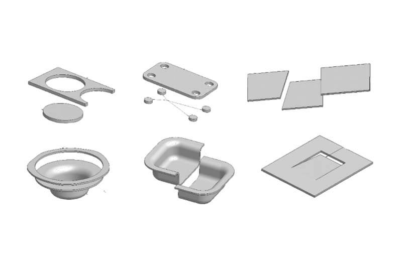
Examples of Automotive Stampings
After learning about the stamping die design fundamentals, now we make the example of the production of stamping parts for automobile stampings to understand the stamping die design fundamentals more clearly.
The processing process of stamping parts for automotive stampings is basically divided into two major categories, namely the separation process and forming process, depending on the shape, size, precision, material, and batch of the parts.
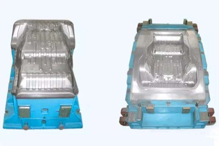
The characteristics of automobile stampings
High-quality requirement of auto stampings manufacturing
Mold manufacturing not only requires high processing accuracy but also requires good processing surface quality.
Generally speaking, the manufacturing tolerance of the working part of the mold should be controlled within plus or minus 0.01mm, and some even require within the micron level.
The surface of the mold after processing not only does not allow any defects but also the surface roughness Ra of the working part is required to be less than 0.4um.
Complex shape of automobile stampings
The working part of the auto stamping die mold is generally a two-dimensional or three-dimensional complex surface, rather than the simple geometry of general mechanical processing.
High hardness of the automobile stamping die material
Automobile stamping die mold is actually equivalent to a mechanical processing tool, its hardness requirements are high, and generally are made of hardened tool steel and other materials, if the traditional mechanical processing methods, often feel very difficult.
Single-piece stamping parts production
Usually, three to five sets of stamping die molds are needed to produce a small number of stamping parts, and stamping dies manufacturing is generally single-piece production.
Each mold made, must start from the die design, and it takes more than one month or even ten months to complete, so the design and manufacturing cycle are relatively long.
Two important processes in automotive stamping die mold manufacturing
Separation process
It means that the stress on the metal plate exceeds the strength limit of the material, causing the plate to shear and crack, and separation occurs. The separation process mainly includes:
Blanking
Using the blanking die to punch along the closed contour curve to separate the part from the blank, and the punching down part is part.
Punching
Using the die to punch along the closed contour curve, the part is separated from the blank, and the punched part is the discarded material, leaving the part as the part.
Extrusion-Shearing
The use of scissors or punching die along the curve of the unclosed contour to cut parts; or the workpiece material part of the cut, but not separated into two parts.
Trimming
The edge of the formed part is trimmed neatly or cut into a certain shape.
The forming process
The sheet metal is subjected to stress exceeding the yield limit of the material so that the sheet plastic deforms and transforms into the required shape of the part. Forming process mainly includes.
Bending
Under the action of external forces, the use of mold bending deformation of the blank to achieve the required shape.
Stretching
Forming flat blanks into various hollow parts, including non-thin stretching and thinning stretching.
Flanging
Turning the edge of a hole or plate stock to produce a flange for strength or for joining.
Expansion
Using pressure to expand smaller diameter hollow parts, tubes, and plates, from the inside out into larger diameter curved bus parts.
Flaring and shrinkage
A forming method that expands or reduces the radial dimension of a hollow blank or a tubular blank on a certain part.
Alignment
It is an auxiliary forming process to eliminate defects in the geometry and size of sheet metal parts after various forming processes, or warpage due to uneven stress after heat treatment so that the shape and size accuracy of the parts meet the design requirements.
Automotive stamping die clamp adjusting basic knowledge
The work scope of the clamp adjuster
Automotive stamping die Mold clamping is the use of various hand tools, drilling machines, and special equipment for the manufacture of molds, through technical processing operations, to complete the current mechanical processing can not complete the process, and will be processed parts, according to the mold assembly diagram for assembly, debugging, and finally made qualified mold products to.
Mold clampers to make good molds must be familiar with, and master the following points.
(1) Familiar with the structure and working principle of the mold.
(2) Understand the technical requirements of mold parts, standard parts, and manufacturing processes.
(3) Master the clamping method of mold parts and mold assembly method.
(4) To understand the use of forming machinery used in the mold and the installation method of the mold on it
(5) Mastering the commissioning method of the mold
(6) Master the maintenance of the mold, maintenance, and repair methods.
The clamp adjuster must master the skills
The ability to read diagrams
Drawing is the basis of mold pliers. Drawing is mainly able to read parts and assembly diagrams, parts diagrams for the clamping process are mainly to reflect the size of the processing surface, relative position, surface tolerance, and processing accuracy.
The assembly diagram mainly reflects the relative position of the parts and the fit tolerance between the parts. Mold assembly in actual operation and general assembly relative to the assembly diagram has a big difference.
Drilling processing
In the mold standard parts, inserts, diagonal covenants, hanging covenants, block, and auxiliary parts fixed or positioning need drilling processing. Drilling processing mainly masters the following aspects.
The correct use of the drilling machine: the use of various buttons and operating handles, the selection of the spindle speed, and the selection of the feed amount.
The sharpening of the drilling method and the influence of the cutting edge angle on the cutting.
Correct clamping of workpieces.
Influence of various materials (cast steel and cast iron) on spindle speed, feed, cutting edge angle, selection of cutting fluid, etc.
Selection of the standard thread bore size and the correct use of taps.
Maintenance and safety matters of drilling machine.
Grinding processing
Use air or electric tools to grind the mold surface.
Gauges
Gage is to measure the actual size of the physical object or between physical objects. Clamp adjustment usually has the following kinds: tape measure (1mm), steel ruler (0.5mm), plug ruler (0.02-1mm), vernier caliper (0.02mm), micrometer (0.01mm), inside diameter percentage table (0.01mm), R gauge. () is the accuracy of the representative ruler.
Assembly
Assembly is an important part of the clamp adjustment. The assembly of the mold and the general clamp assembly is very different.
General clamp assembly only needs to be installed in accordance with the assembly diagram, generally regarded as static assembly, while most of the mold assembly belongs to the dynamic assembly, generally considering the working condition of the press and heat treatment after the deformation.
The following are some common types.
(1) Die base guide plate installation
Find the relative position of the guide plate by pressing it against the face of the mountain, find the center point of the hole with a sample punch, and then drill and tap the hole. In addition, check the rate of the guide plate and the mounting surface.
After the installation of the guide plate, check the clearance between the upper and lower die base guide plate, the clearance of the outer guide plate is within 10 courses, and the inner guide plate is within 8 courses.
(2) Installation of the slanting part of the lifting die
The crane is divided into 3 parts: mounting slot, sliding part, and driving seat. Their benchmark is the mounting slot, the sliding part is standardized by the mounting slot, and the driving seat is standardized by the CNC and sliding part.
The convex die of the slant die (hanging die) is coarsely referenced to the CNC, and then the side clearance is adjusted on the press.
The effective contact surface of the guide plate on the inclined die (hanging die) and the mounting surface should be more than 80%.
The side clearance of the guide plate is 3 (below 500) or less; above 500 is 5 or less.
The clearance of the upper guide plate is within 2 (below 500); above 500 is within 3, and the flexibility of movement between them should be ensured at the same time.
(3) Installation of trim die block
The installation of the trimming block is the installation and local adjustment after the rough machining and quenching in the assembly workshop. Firstly, make an adjustment to the surface and cavity, including the trimming of the surface and gap and the trimming of the gap between the blocks.
If there is a cushioned surface, the cushion surface will be used as the benchmark, and if there is no cushion surface, the position of several inserts will be determined, usually diagonally. Then finish machining.
(4) Positioning of punching die convex die (punching pin)
Since the side clearance of the convex and concave dies is only 3 channels, there are errors in both CNC point finding and manual drilling and tapping (especially the latter), so it is difficult to locate them precisely, and the only way to locate them manually, in this case, is in the dynamic situation of the press.
The general method: for cylindrical type, find one point in the CNC machine; for non-cylindrical type, find two points in the CNC machine for drilling and tapping to rough positioning.
For precise positioning, put putty on the convex die, apply red-dan powder on the relative concave die, find the precise position by the press, and finally use the positioning pin to locate.
(5) Assembly of scrap cutter
The assembly of the scrap cutter is somewhat similar to that of the punching die. Since the scrap knife changes after the trimming model surface and cavity adjustment, and sometimes it is very large, it is positioned purely by hand.
First, put the die on the press, put the scrap knife against the cavity, find out the position of the scrap knife with a scribing needle, and then find out the precise position after drilling and tapping.
The above (4) and (5) are used to achieve the requirement by having a 1.5 pass margin between the screw and the hole.
Adjustment
Adjustment is the most important part of the clamping process, adjustment is to enable the mold to process a qualified part, can enhance the performance of the mold, and service life, and provides some accurate parameters for the debugging process, adjustment, and assembly are often carried out at the same time.
Before adjustment, one should first master the type of mold, structure, the shape of the parts, and relative reference frame. Adjustment is divided into static adjustment and dynamic adjustment.
Static adjustment mainly includes the adjustment of research rate and surface roughness. Dynamic adjustment includes the adjustment of various guide pillars, guide bushings, and guide plate clearance; the adjustment of the grinding rate of the guide plate, slanting cage (hanging cage), and the mounting surface and the cleaning surface.
Adjustment of the gap between the trimmer cavity and the press ring, and adjustment of the gap between the inserts.
Adjustment of all die movement strokes; commissioning of press pressure.
Adjustment of various inlays and scrap knives.
Rounding the transition surface of the drawing dies, punching and releasing material, etc.
The impact of various factors on the mold.
(1) The influence of the research rate
The poor research rate of the drawing die and plastic dies will produce defects of uneven thickness of parts, pulling cracks or wrinkles or inaccurate size of parts; the defects of the trimming die, plastic die, and punching die will produce defects of misalignment, strain and pulling crack of parts.
(2) The impact of roughness
It is easy to cause scratches on the surface of the parts; especially for the drawing die, if the surface roughness is too high, it will cause high resistance to drawing, resulting in strains or cracks in the parts.
The surface roughness of the drawing die should reach 0.8 or even higher for the drawing inlay and transition inflection point.
(3) The impact of the gap between the standard parts
If the gap is too small, it will cause strain on the surface of the standard parts; if the gap is too large, it will cause the relatively moving part with larger misalignment, and it will affect the service life of the mold.
(4) Influence of drawing die pressure
If the pressure is too large, it will cause the pulling crack or thinning of the parts, too small, resulting in pulling wrinkles. For double-action press, if the external pressure is too large, it will cause the pulling of the situation.
Many factors affecting the parts failed, and the cause of the cause can only be comprehensive analysis to exclude one by one, mainly by the accumulation of experience.
In the adjustment of the research, the rate must pay attention to the benchmark of the mold. General convex die as the benchmark, the benchmark can only be surface roughness and burr repair, do not allow for grinding or change of surface.
The use of presses
There are hydraulic presses and mechanical presses used for molds.
Hydraulic presses are generally used for drawing dies; mechanical presses are used for other dies. For a single mold on the press, attention should be paid to the movement of the press circle, and when adjusting downward, do not adjust too much at one time, so as not to cause damage to the mold.
For mechanical presses, positioning blocks and sludge are commonly used to limit and check the position. For the drawing die, the press pressure should first be based on the design pressure, and then adjusted gradually in small amounts.
Before the die is put on the press, it should be checked whether the die is clean, whether the screws are tightened, whether the parts of the debugging part are assembled completely; whether the press is normal, etc.
Safety matters
The clamping is a special type of work, there are various safety hazards. Should adhere to the “safety first, prevention first” policy.
Mold clamper’s safety hazards are drill press, overhead crane, various abrasives used, press, noise, road slip, etc.
Should not hurt others, not be hurt by others, not hurt themselves, improve their own vigilance, and enhance their safety awareness and skills.
Common parts defects
The main defects of the parts are pulling cracks, pulling wrinkles, strain, local thinning, deformation, burr, etc.
There are many reasons for parts defects, such as whether the design is reasonable, whether the process is appropriate, the material’s ability to resist tensile and compressive deformation, the surface roughness of the mold, rounding angle, research rate, flatness, the accuracy of the movement gap, etc.
Besides the Stamping Die Design Fundamentals and Examples of Automotive Stampings article, you may also be interested in the below articles.
Summary Of 50 Injection Mold Structure Operation Dynamic Diagrams
What Is The Difference Between Two-Platen Mold And Three-Platen Mold?