Bushings


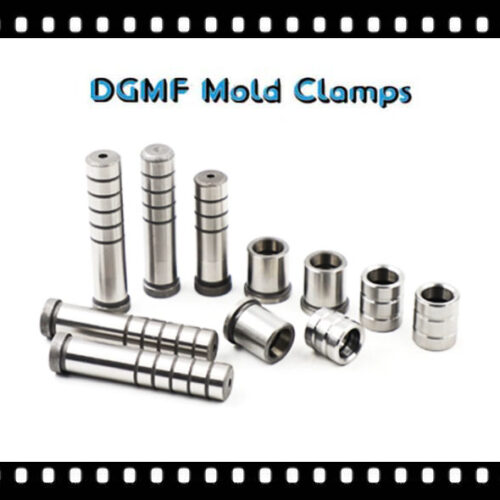
Injection Mold Bushings Supplier
DGMF Mold Clamps Co., Ltd is the injection mold bushings supplier and mould clamps manufacturer in China.
What is the bushing in injection mold?
The bushings are important mold components in the injection molding field, the bushing series include guide bushing, sprue bushing, etc.
Guide Bushing
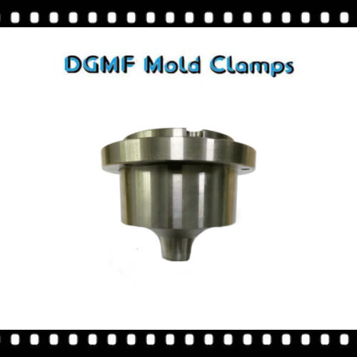
The guide bushing is a mold component used in conjunction with the guide pin to play a guiding role.
Generally, the fit-gap is very small, within 0.05mm; it is generally used in molds or some machinery to ensure the accuracy of movement.
Mold guide bushing
The mold guide bushing, also known as (mold guide sleeve, high-strength brass bearing) is on the base of high-strength brass. A high-performance solid lubricating product embedded with graphite or MoS2 solid lubricants. It breaks through the limitations of general bearings that rely on oil film lubrication.
During use, the solid lubrication and the shaft are rubbed by frictional heat, forming an excellent condition for the coexistence of oil and powder lubrication, which not only protects the shaft from wear but also makes the solid lubrication properties eternal. Its hardness is twice as high as that of ordinary copper sleeves, and its wear resistance is also twice as high.
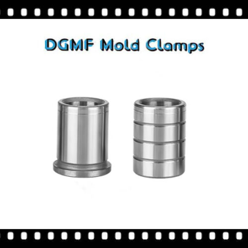
Guide bushing shape
There are basically 5 shapes of solid-inlaid bearings, which are straight guide bushing, flange guide bushing, slider, thrust washer, and bearing bush. Good hardness performance, high wear resistance, no oil can be used, high load, low speed, can play a superior performance, superior chemical resistance, corrosion resistance, flexible design, simple, convenient, rich standards It can be used with the standard shaft.
Guide bushing application
It is widely used in metallurgical continuous casting machines, train supports, steel rolling equipment, mining machinery, ships, steam turbines, and other high temperature, high load, low speed, and heavy load occasions.
Guide bushing material
The bearing steel SUJ2 pipe material imported from Japan’s original factory is processed into a mold guide pin guide bushing that acts as an initial guide when the upper and lower molds are closed.
Suitable for stamping molds, high-speed progressive stamping molds, hardware molds, plastic molds, and other environments. It can be used for hardware die, electronic connector dies, fin dies, stator and rotor silicon steel sheet die, etc.
Guide bushing specifications
For the performance of the mold guide pin and guide bushing, all aspects such as rigidity, wear resistance, concentricity, cylindricity, and fit and fit can be required.
The specifications of the stock guide pin and guide bushing components are (20*55-160), (22*55-180), (25*65-180), (28*75-200), (32*120-200), ( 36*135-220), (38*135-220), (45*135-220), (50*155-220).
Sprue bushing
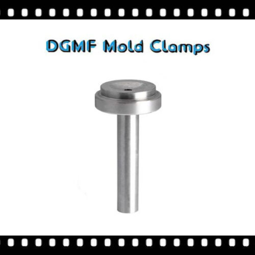
The sprue bushing is a metal fitting used by the plastic mold to connect the molding mold and the injection molding machine.
The sprue bushing is a component of the runner that allows the molten plastic material to be injected from the nozzle of the injection molding machine into the mold, and is used to connect the molding mold and the metal fitting of the injection molding machine.
The sprue bushing can also be described as a runner component that allows molten plastic material to be injected from the nozzle of the injection molding machine into the mold.
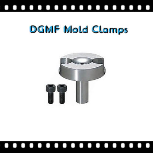
The bolt-type sprue bushing is a sprue bushing fixed with 2 bolts, which can be fixed by bolts to prevent the nozzle from falling off due to injection pressure.
Type of sprue bushing
According to the different appearance, the sprue bushing can be divided into A-type sprue bushing, B-type sprue bushing, C-type sprue bushing, D-type sprue bushing, E-type sprue bushing, small gate sprue bushing, big gate sprue bushing, etc.
Three types of A, B, and C sprue bushing are commonly used. Type A sprue bushing has a special bolt fixing interface, which is fixed by bolts to prevent the sprue bushing from falling off due to excessive injection pressure.
Sprue bushing standard
The manufacturing standard of the mouthpiece: JIS general-purpose type, namely MISUMI, HASCO, DME, GB, etc.
Sprue bushing manufacturing materials
1. SKD61 hot work die steel can produce high-end and very durable sprue bushings with a hardness of 48~52HRC. The sprue bushing made of SKD61 has the characteristics of high-temperature resistance and durability, and excellent quality of molded products.
2. SUJ2 bearing steel is a commonly used manufacturing material for the middle-end sprue bushing, and its heat treatment hardness is about ±HRC52.
3. S45C, the material used in low-end molds, needs to be sprayed with anti-rust treatment such as anti-rust oil after high temperature to prevent rust.
4.HPM1 etc.
The sprue bushing made of hot-work die steel has the characteristics of heat resistance, wear-resistance, and durability; in order to prevent the leakage of plastic materials, the feed inlet is generally designed as an R-angle arc flow transition.
The influence of sprue bushing and the choice of position
Gate position requirements
1. Appearance requirements (gate marks, weld lines)
2. Product functional requirements
3. Mold processing requirements
4. Warpage of the product
5. The gate volume is not easy to remove
Impact on sprue bushing production and function
1. Flow (Flow Length) determines the injection pressure, clamping force, and the filling of the product
Short flow length can reduce injection pressure and clamping force
2. The gate position will affect the holding pressure
Holding pressure
Is the holding pressure balanced?
Keep the gate away from the future force position of the product (such as the bearing) to avoid residual stress
Exhaust gas must be considered at the gate location to avoid wind accumulation. Do not place the gate at a weak or embedded part of the product to avoid deviation (Core Shaft)
Tips for choosing gate location
1. Place the gate at the thickest part of the product, pouring from the thickest part can provide a better filling and pressure holding effect.
If the holding pressure is insufficient, the thinner area will solidify faster than the thicker area.
Avoid placing the gate where the thickness changes suddenly to avoid hysteresis or short shots.
2. If possible, pour from the center of the product
Placing the gate in the center of the product can provide equal flow length.
The size of the flow length will affect the required injection pressure
The central pouring makes the holding pressure uniform in all directions and avoids uneven volume shrinkage.
3. Gate
The gate is a short groove with a small cross-sectional area to connect the runner and the mold cavity. So the cross-sectional area is small, and the purpose is to obtain.
The following effects
1. Soon after the cavity is injected, the gate will be cold.
2. Easy to remove water.
3. The dewatering port is completed, leaving only a few traces
4. Make the filling of multiple mold cavities easier to control.
5.Reduce the phenomenon of excessive filler.
There are no hard and fast rules for the method of designing gates. Most of them are based on experience, but there are two basic elements that must be compromised.
1. The larger the cross-sectional area of the gate, the better, and the shorter the length of the channel, the better to reduce the pressure loss when the plastic passes.
2. The gate must be thin and narrow in order to be easy to freeze and prevent excessive plastic from flowing back. Therefore, the gate is in the center of the runner, and its cross-section.
It should be as round as possible. However, the gate switch is usually determined by the switch of the module.
Gate size
The size of the gate can be determined by the cross-sectional area and the length of the gate. The following factors can determine the best size of the gate.
1. Rubber flow characteristics
2. The thickness of the module
3. The amount of rubber injected into the cavity
4. Melting temperature
5. Mold temperature
When determining the gate location, the following principles should be adhered to.
1. The rubber injected into each part of the cavity should be as even as possible.
2.The rubber material injected into the mold should maintain a uniform and stable flow frontline at all stages of the injection process.
3. The possible occurrence of weld marks, bubbles, cavities, vacant positions, insufficient injection, and spraying should be considered.
DGMF Mold Clamps Co., Ltd manufactures the mold clamps and supplies the injection mold components, such as Clamps, Toggle Clamps, C Clamps, Pins, Bushings, Positioning Components, Lock Mold Components, Reset Extrusion, Cavity, and Core Components, Coolings, Die Press Components, Punch And Die, Guide Components, Self-lubricating Components, Springs, Machine Tools, Machine Mounts, gate valves, Vises, Fasteners, Lifting, Bolts, Nuts, Washers, etc.
Contact the DGMF Mold Clamps teams for more details about the injection mold bushings such as injection mold bushings specifications, mold bushings pricing, bushings inventory, etc.
Showing all 7 results