This article discusses the 12 Types of Gates in Injection Moulding and how to select the right types of gates in injection moulding.
What is an injection moulding gate?
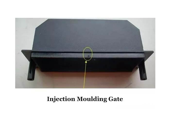
The gate of a plastic injection mould is a short section of the runner between the manifold and the cavity, which is the entrance of the resin into the cavity.
The shape, number, size, and position of the gate in the mould will greatly influence the quality of the plastic part.
Therefore, selecting a gate is one of the key points of plastic injection mould design, and the following is the introduction of the gate in several aspects.
What is the function of the injection moulding gate?
The main role of the injection moulding gate is.
- After filling the cavity, the melt will condense at the gate to prevent it from backflowing.
- It is easy to remove the tail material of the gate.
- For multi-cavity moulds it is used to control the position of the fusion trace.
What are the types of gates in injection moulding?
There are generally divided into two injection moulding gates: non-restrictive and restrictive. Restrictive gates are divided into 3 series: side gates, point gates and disc ring gates.
Non-restrictive gates in the 12 types of gates in injection moulding

The non-restrictive gate direct gate in the 12 types of gates in injection moulding.
The non-restrictive gate is also called the direct gate. Its characteristic is that the plastic melt flows directly into the cavity, the pressure loss is small, the feeding speed is fast, and the moulding is easy.
It is suitable for all kinds of plastics. It has the advantages of good pressure transfer, strong pressure retention and shrinkage, simple and compact mould structure, and convenient manufacturing.
However, it is difficult to remove the gate, and the gate marks are obvious; the heat concentration near the gate is slow to condense and easy to produce large internal stress, and also easy to produce shrinkage pits or surface indentation. It is suitable for large plastic parts, thick-walled plastic parts, etc.
Restricted gates in the 12 types of gates in injection moulding
A channel connects the cavity and the manifold with a short distance and a small cross-section. The main types of restrictive gates are the below showing.
Point gate in the 12 types of gates in injection moulding

Point gate in the 12 types of gates in injection moulding
A point gate is a circular gate with a very small cross-section.
The characteristics of a pointed gate are.
- Small restriction on gate position.
- Small residual traces after removing the gate do not affect the appearance of the moulded part.
- The gate can be pulled off automatically when the mould is opened, which is good for automatic operation.
- The sprue accessory filler causes small stress.
Disadvantages:
With large pressure loss, the mould must adopt a three-plate mould structure. The mould structure is complicated, and a sequential mould-splitting mechanism should exist. It also can be applied to a two-plate mould structure without a runner.
Latent gates in the 12 types of gates in injection moulding
The submerged gate evolved from the point gate. The manifold is opened on the parting surface, and the gate is submerged under the parting surface and enters the cavity along the oblique direction. The submerged gate has the characteristics of the point gate.
The feeding gate is usually on the inner surface or side of the plastic part, so it does not affect the appearance of the plastic part. The plastic part and the runner are set to push out the mechanism, the gate is automatically cut off when the mould is opened, and the condensed material of the runner automatically falls off.
Side gate in the 12 types of gates in injection moulding

Side gate/Edge gate in the 12 types of gates in injection moulding.
Side gates also called edge gates in injection moulding, are generally opened on the parting surface and feed from the outside of the cavity (plastic part). The side gate is a typical rectangular cross-section gate, which can easily adjust the shear rate and gate closing time during mould filling, and is therefore also called a standard gate.
Side gates are characterized by simple gate cross-sectional shape, easy processing, and precise gate dimensions machining; flexible gate position selection to improve the mould filling condition; correction without unloading the mould from the injection moulding machine; easy removal of the gate and small traces.
Side gates are especially suitable for two-platen multi-cavity moulds. However, it is easy to form defects such as fusion marks, locking holes, and depressions, and it has high injection pressure loss and poor exhaust for shell-shaped parts.
Overlapping gate in the 12 types of gates in injection moulding

Overlapping gate or Lap gate in the 12 types of gates in injection moulding.
An overlapping gate, also called a lap gate, is the same as a side gate, but the gate is not on the side of the cavity but on one side of the cavity.
It is a typical impact gate, which can effectively prevent the injection flow of the plastic melt. If the moulding conditions are improper, surface pits can be created at the gate. It is difficult to cut the gate and will leave obvious gate marks on the surface of the moulded part.
Fan gate in the 12 types of gates in injection moulding

Fan gate in the 12 types of gates in injection moulding
Fan gate is a variation of the side gate and is often used for moulding large-width plate parts. The gate gradually widens in the feeding direction, and the thickness gradually reduces to the thinnest.
The plastic melt is evenly distributed in the width direction, which can reduce the internal stress and warpage of the moulded part; the cavity has good exhaust volume to avoid surrounding air. However, it is difficult to remove the gate, and the trace is obvious.
Film gate in the 12 types of gates in injection moulding
A film gate is a variation of the side gate and is often used for injection moulding large flat parts. The distribution runner of the film gate is parallel to the side of the cavity, called a parallel runner, and its length can be greater than or equal to the width of the moulded part.
The plastic melt is distributed evenly in the parallel flow channel. Then it flows parallel to the cavity at a lower linear velocity so that the moulded part’s internal stress is low, the warpage deformation caused by orientation is reduced, and the cavity is well-ventilated. However, the gate removal workload is large, and the traces are obvious.
Disc-shaped gates in the 12 types of gates in injection moulding
Disc gate is used for cylindrical plastic parts with large or square bores. The gate is on the entire perimeter of the bore. The plastic melt enters the cavity from the perimeter of the bore at approximately the same speed.
The plastic part does not produce fusion marks, the core is uniformly stressed, and the air is removed in sequence. For our products, disc-shaped gates are rarely used.
Circular gates in the 12 types of gates in injection moulding
The circular gate is set on the outer side concentric with the cylinder cavity, i.e. the gate is set around the cavity, so it can be called the outer circular gate, and its gate position corresponds to the inner disc gate. It is suitable for thin-walled long tube line plastic parts.
Since the melt enters the cavity evenly around the core, the mould is filled evenly, the exhaust effect is good, and the part has no melt marks. However, it is difficult to remove the gate, and it leaves obvious gate marks on the outside of the part. Circular gates are mostly used in small, multi-cavity moulds.
Spoke gate in the 12 types of gates in injection moulding
It is a spoke-type gate with a similar scope of application as the disc-shaped gate and applies to the moulded parts with the rectangular bore. It is a change of the whole peripheral feed into several small arcs or straight lines so that it can be regarded as an inner gate.

Spoke gate and Claw gate in the 12 types of gates in injection moulding.
Claw gate in the 12 types of gates in injection moulding
The claw gate is a variation of the spoke gate, which opens a runner in the conical section of the core. It is mainly used for long tubular parts with small bores or high coaxiality requirements.
How to select the right types of gates in injection moulding?
The location and number of gates often determine the quality of the product’s appearance and performance, so the following points should be followed when choosing the location and number of gates.
- The gate should be located in a position where all corners of the cavity can be filled at the same time;
- The plastic injected into the cavity should maintain a uniform and stable flow rate at all stages of the injection process.
- The gate should be set in the thick part of the product wall thickness so that the melt flows from the thick section into the thin section to facilitate material replenishment and ensure complete mould filling.
- The gate location should be chosen so that the plastic filling process is as short as possible to reduce pressure loss.
- The location of the gate should be chosen in a part that is conducive to the exclusion of gas from the cavity;
- The gate should not allow the melt to rush straight into the cavity. Otherwise, it will produce a swirling flow and leave swirling traces on the moulded part, especially if the gate is narrow;
- Consideration should be given to the possibility of fusion marks, bubbles, sags, dips, undershot and spraying;
- The gate’s location should be chosen to avoid fusion lines on the product’s surface. When fusion lines cannot be avoided, the location of the gate should be chosen to the suitability of the area where the fusion lines will occur;
- The location of the gate should be chosen in such a way as to prevent the creation of stitching lines on the surface of the plastic, especially in the case of circular or cylindrical parts, by opening a cold well on the face of the gate where the melt is poured.
- The sprues should be set in such a way as to avoid melt fractures.
- When the projection area of the product is large, avoid opening the gate on one side to prevent uneven injection forces.
- Gates should be set in areas that do not affect the product’s appearance.
- Do not set gates on product parts subject to bending or impact loads. Generally, the strength of the product near the gate is the worst;
- For injection moulds with long, thin cores, the gate should be located far from the core so that the flow of material does not deform the core;
- Compound gates can be used to prevent warping, deformation and lack of material when forming large or flat moulded parts.
- The operation of the sprue should be as easy as possible, preferably automatic.
Besides the 12 Types of Gates in Injection Moulding article, you may also be interested in the below articles.
Summary Of 50 Injection Mold Structure Operation Dynamic Diagrams
What Is The Difference Between Two-Platen Mold And Three-Platen Mold?