Coolings
-
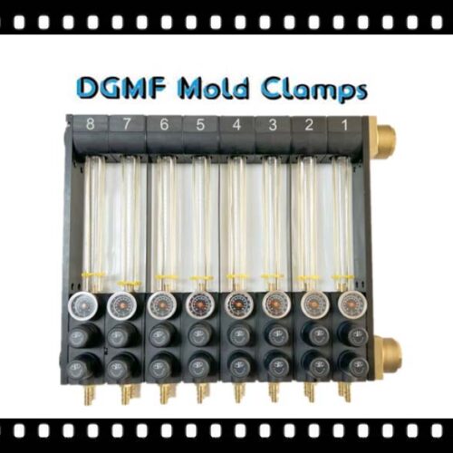
DGMF Water Flow Regulators for Plastic Injection Molding
Read more -
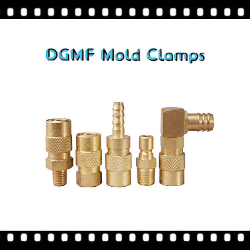
DGMF Quick-release Hose Connectors
Read more -
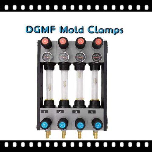
DGMF Precision Water Flow Regulator Injection Moulding
Read more -
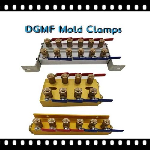
DGMF Mold Cooling Water Manifold With Valves
Read more -
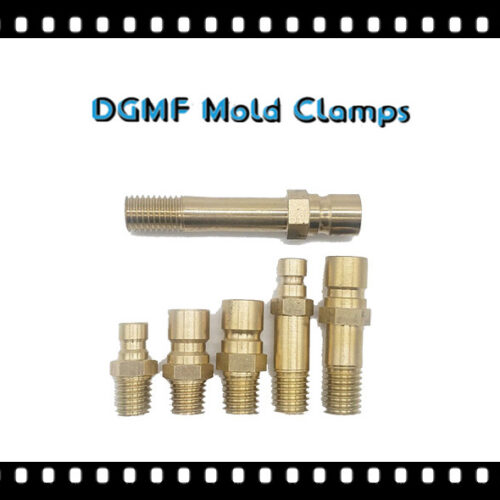
DGMF Mold Cooling Hose Nipple Pipe Fittings
Read more -
DGMF Cooling Joint Plugs JTWS HX JTW1/2/3-50/75/100/125/150/175/200/250/300
Read more -
DGMF Cooling Circuit Plugs For Injection Mold Cooling
Read more -
DGMF Cascade Water Junctions Mold Cooling Pipes
Read more -
DGMF Baffle Boards Mold Cooling Components
Read more -
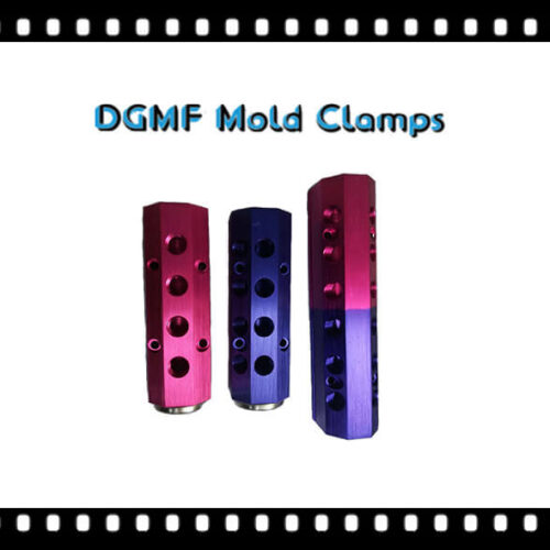
DGMF Aluminum Water Manifolds For Plastic Injection Molds
Read more -
DGMF Air Poppet Valves Air Poppets
Read more
Cooling System Components Supplier
DGMF Mold Clamps Co., Ltd is the cooling system components supplier, mold clamps supplier, and mould clamps manufacturer in China.
The water transportation of the mold is the share of the cooling system in the mold, if not, it will affect many aspects.
1. The Influence Of Mold Humidity On Plastic Parts
There are many factors that affect the cooling of the injection mold, such as the shape of the plastic part and the design of the parting surface, the type, temperature, flow rate of the cooling medium, the geometric parameters, and spatial arrangement of the cooling pipe, the mold material, the melt temperature, and the top required by the plastic part.
The output temperature and mold temperature, the thermal cycle interaction between the plastic part and the mold, etc.
(1) Low mold temperature can reduce the molding shrinkage of plastic parts.
(2) Uniform mold temperature, short cooling time and fast injection speed can reduce the warpage of plastic parts.
(3) For crystalline polymers, increasing the mold temperature can stabilize the dimensions of the plastic parts and avoid post-crystallization, but it will lead to the defects of prolonged molding cycles and brittle plastic parts.
(4) As the crystallinity of the crystalline polymer increases, the stress crack resistance of the plastic decreases, so it is advantageous to lower the mold temperature.
However, for high-viscosity amorphous polymers, due to their resistance to cracking is directly related to the internal stress of the plastic part, it is advantageous to increase the mold temperature and filling speed and reduce the refilling time.
(5) Increasing the mold temperature can improve the surface quality of plastic parts.
2. Determination Of Mold Temperature
During the injection molding process, the mold temperature directly affects the filling of the plastic, the shaping of the plastic part, the molding cycle, and the quality of the plastic part.
The mold temperature depends on the crystallinity of the plastic, the size and structure of the plastic part, performance requirements, and other process conditions such as melt temperature, injection speed, injection pressure, and molding cycle.
For amorphous polymers, the melt solidifies as the temperature decreases after being injected into the mold cavity, but no phase transition occurs. The mold temperature mainly affects the viscosity of the melt, that is, the filling rate.
Therefore, for amorphous plastics with low and medium melt viscosity, such as polystyrene, cellulose acetate, etc., using a lower mold temperature can shorten the cooling time.
For plastics with high melt viscosity, such as polycarbonate, polyphenylene ether, polysulfone, etc., a higher mold temperature must be adopted to avoid defects such as cold flow marks and dissatisfaction. At the same time, due to its higher softening temperature, the mold temperature is increased。
The cooling rate of the plastic parts can be adjusted to make them uniform, so as to prevent the plastic parts from causing dents, internal stress, and cracks due to excessive temperature differences.
After the crystalline polymer is injected into the mold cavity, it begins to crystallize when the temperature drops below the melting point. The rate of crystallization is controlled by the cooling rate and ultimately the mold temperature.
High mold temperature will lead to a large crystallization rate, which is conducive to the relaxation process of molecules, so the size is stable but the plastic parts are brittle, and it is suitable for plastics with a small crystallization rate such as polyethylene terephthalate.
Low mold temperature will lead to a decrease in molecular crystallinity in plastic parts. For plastics with glass transition temperatures below room temperature, such as polyolefins, post-crystallization will occur, which will cause changes in size and mechanical properties. Suitable mold temperature range, moderate cooling rate, and moderate crystallization and orientation of molecules.
3. Design And Analysis Of Injection Mold Cooling System
3.1 Principles Of The Design Of The Injection Mold Cooling System
The design of the cooling system needs to consider the structure of the mold, the size and wall thickness of the plastic part, the position of the insert, and the location of the weld mark.
(1) The thickness of the plastic part is uniform, and the distance from the cooling channel to the surface of the cavity is equal, that is, the arrangement of the cooling channel is consistent with the shape of the cavity.
The cooling channel at the wall thickness of the plastic part should be close to the cavity, and the spacing should be small to enhance cooling. Generally, the distance between the cooling channel and the cavity surface is greater than 10mm, which is 1 to 2 times the diameter of the cooling channel.
(2) As long as the mold structure allows, the aperture of the cooling channel should be as large as possible, and the number of cooling circuits should be as large as possible to ensure uniform cooling.
(3) In order to prevent water leakage, cooling channels should not be provided at the joints of the inserts and inserts, and attention should be paid to the sealing of the water passage through the core, the sealing of the joint between the cavity and the template, and the sealing of the connection between the water pipe and the water nozzle.
The water pipe joint is set in a direction that does not affect the operation, usually in the north of the injection machine.
(4) Cooling should be strengthened at the gate. Due to the highest temperature near the gate, the cooling water can usually flow through the vicinity of the gate first, and then to the far end of the gate.
(5) Reduce the temperature difference between the inlet and outlet water to avoid uneven cooling of the mold surface.
(6) The cooling channel should avoid being close to the production position of the plastic part weld line, so as not to reduce the strength of the plastic part.
(7) There should be no water storage and backflow in the cooling channel, and excessive pressure drops should be avoided. The diameter of the cooling channel should be easy to process and clean, generally φ6~φ12mm.
3.2 Cooling Analysis Of Injection Mold
Because the shape of the actual plastic parts is often very complicated, there are great limitations in analyzing the feasibility of the cooling system using some simplified formulas or empirical formulas.
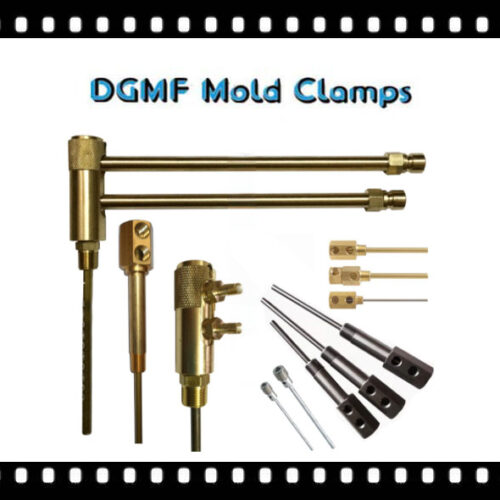
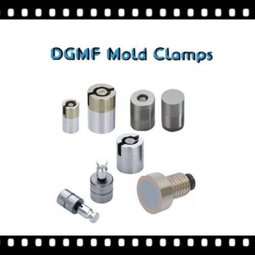
The mold cooling system components are including mold nipples, quick-release connector plugs, spiral brass plug baffles, cooling circuit plugs, shoulder bolts, screw plugs, O-rings, cooling pipes, etc.
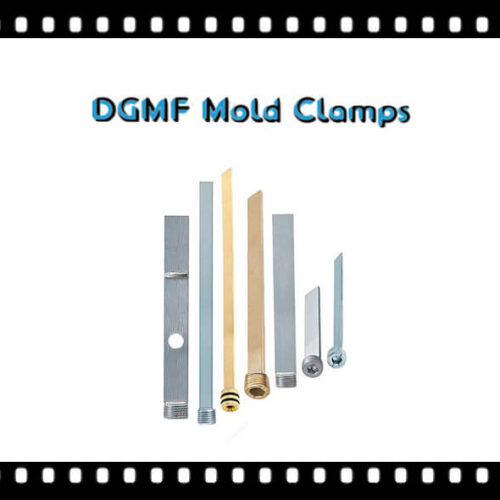
Mold Brass Plug Baffle
The mold brass plug baffle can be installed quickly to reduce the time of up and down the mold, establish a failure mode and impact analysis library, and prevent water.
The role of brass plug baffle in injection mold
The brass plug baffle is generally installed in the mold with a longer protrusion or inside the core. The core should not be drilled on the outer surface. Only one hole can be drilled at the bottom, and then separated by a beryllium copper sheet to form a water transport circuit. To achieve the cooling effect.
DGMF Mold Clamps Co., Ltd supplies brass plug baffles of various specifications of the mold, there are two types of straight brass plug baffles and spiral brass plug baffles, and HASCO and DME specifications can be customized.
Quality Inspection Problem
1. Establish the processing technology for the mold brass plug baffle, and summarize the mold parts list, purchased parts list, standard parts list, self-made parts list, self-made standard parts list, material list, heat treatment parts list, The list of wearing parts, and mold costs to ensure that relevant resources can be in place in time.
2. Combine production plan management and schedule management to ensure that relevant equipment can be used effectively, prevent personnel from being idle, and enable all links in processing and manufacturing to be linked together.
3. Establish failure mode and impact analysis library
Establish a mold design, manufacturing failure mode, and impact analysis library, and prevent the same problem from appearing next time through meetings, announcements, and computer sharing, plus rewards and penalties.
Mold Cooling Component Baffle Boards Advantage
1. Quick installation, reduce the time of up and down molds, and improve work efficiency.
2. The water flow is uniform to ensure product quality and efficiency of injection molding, die casting, and blow molding.
3. Price advantage, quality assurance, only about 30% of the original price can have original products, to improve competitiveness.
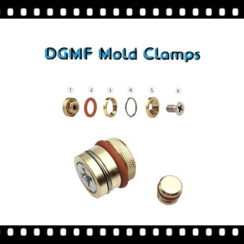
Cooling Circuit Plugs
The Cooling Circuit Plug is a metal part that is used in plastic molds or any waterway cooling or heating system to match the required flow direction to play a role in filling.
Application Range Of Cooling Circuit Plug
Plastic molds, water channel cooling system, and water channel heating and heat conduction system.
The working principle uses the slope principle,
Scope of use Plastic mold, water channel, and runner cooling system
Cooling Circuit Plugs For Injection Mold Cooling Features
No need for tapping, never rust;
Cooling circuit plug, runner, and waterway heating and heat conduction system.
The cooling circuit plug enlarges the O-ring and the shrapnel to fill the role.
The elasticity can be adjusted at will, no antidiarrheal belt is needed;
It can be moved at will and placed anywhere in the water channel;
As the water is heated, the water is also heated, and the thermal conductivity is good, and the heating and cooling of oil materials are the same.
Endurance of Cooling Circuit Plug
The diameter is 8mm or more than 16KG/square centimeters;
Diameter 10mm or more than 17KG/square centimeter;
Diameter 12mm above 19 kg/square centimeter.
Precautions For The Use Of Cooling Circuit Plug
1. The aperture of any specification mold should be 0.1mm larger than the outer diameter of the stopcock;
Example: 8mm (outer diameter) stop plug, its mold hole should be 8.1mm
2. If the cooling circuit plug is not positioned in the waterway, you can relax it first, and then spray it with an air gun to reposition it.
Working environment: general temperature -5℃~+135℃
The working temperature of the special cooling circuit plug -10℃~+280℃
Hex Socket Plug
The hex socket plug is a kind of fastener. The hex socket plug is a kind of set screw plug. The flat-end set screw plug is similar, but the inner hexagon of the hex socket plug is slightly larger. It is a PG1.5 set screw hex socket plug.
Hex Socket Plug Applications
Hex socket plugs are practically used in various hydraulic machinery such as cylinders, pump oil, hydraulic valves, hydraulic stations, diesel engines, etc.
Socket pressure plugs provide a pressure-tight seal in pneumatic and hydraulic applications. Threads are specially designed to prevent spiral leakage.
DGMF Mold Clamps Co., Ltd supplies the BSPT Hex Socket Pressure Plug, NPT Hex Socket Pressure Plug, GB Metric Hex Socket Pressure Plug, etc.
In addition to high-quality carbon steel and alloy steel, the production materials also include high-quality stainless steel such as 304, 316, and 410.
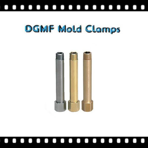
Cooling Pipe
The mold water cooling pipe is a mold part that participates in cooling through cooling water.
The main function of the mold water cooling pipe is to cool the mold core from the inside.
Cooling Pipe Characteristics
For cooling components, mold temperature control is a very important factor in improving the dimensional precision of formed products, maintaining the stability of physical properties, and shortening the forming cycle.
1. The cooling water pipe is a new and efficient standard component of the plastic mold cooling system;
2. By designing the cooling water inlet and outlet ports in different directions, the cooling water is brought to the depth of the mold that needs to be discharged, and the cooling water flows quickly to take away the heat so that the mold temperature is uniform and moderate;
3. Numerous specifications and models can be applied for different occasions.
Spiral Water Cooling Pipe
Performance characteristics
1. The spiral water cooling pipe is a new and efficient standard part of the plastic mold cooling system;
2. The spiral water cooling pipe is made of aluminum material, which has good rigidity and temperature resistance;
3. The spiral structure design of the cooling pipe makes the cooling water circulate rapidly in the mold cooling water channel to take away the excess temperature, thereby continuously and uniformly controlling the mold temperature;
4. The spiral cooling pipe replaces the traditional plastic cooling pipe, avoiding the shortcomings of insufficient strength and poor temperature resistance, and has better strength and temperature control capabilities than other types of mold brass plug baffles;
5. The water inlet and outlet modes can be reprocessed by themselves to ensure reasonable use on various occasions;
6. Convenient and simple installation and disassembly.
Whether a set of plastic mold temperature controls is good or bad will directly affect the quality of injection products.
The main purpose of setting the cooling water circuit in the plastic mold is to control the temperature of the mold to make the injection molded product have good product quality and higher productivity.
Existing molds are generally equipped with a cooling system, which is mainly composed of a cold water moving device connected with a water transport circuit set on the injection mold.
Under the action of water transport, the mold temperature is maintained to prevent the product from overheating in the injection mold.
Deformation occurs, making the injection size of the product more stable.
The product can be cooled and solidified faster in the mold, shorten the production cycle of the product, and improve production efficiency.
Whether the water transportation circuit is designed properly or not has an extremely important impact on product quality.
O-ring
O-rings are rubber sealing rings with a circular cross-section. Because the cross-section is O-shaped, they are called O-rings, also called seal rings. It began to appear in the middle of the 19th century when it was used as a sealing element for steam engine cylinders.
Because of their low price, simple manufacturing, reliable function, and simple installation requirements, O-rings are the most common mechanical design for sealing. The O-ring bears a pressure of tens of megapascals (thousand pounds).
O-rings can be used in static applications, but also in dynamic applications where there is relative movement between components, such as the shaft of a rotary pump and the piston of a hydraulic cylinder.
O-ring Specifications And Standards
O-ring specifications include UHSO-ring specifications, UHPO-ring specifications, UNO-ring specifications, DHO-ring specifications, piston rod O-ring specifications, high-temperature-resistant O-rings, high-pressure-resistant O-rings, and corrosion-resistant O-rings Ring, wear-resistant O-ring.
O-ring standards mainly include national standard GB 1235-76, national standard GB3452.1-92; Japanese standard P TYPE, G TYPE, S TYPE, SS/V TYPE, F TYPE; American standard AS568, British standard series; European standard series
The technical requirements for O-rings include appearance requirements, size requirements, and material physical performance requirements.
Appearance requirements comply with GB/T3452.2-2007
Material requirements meet HG/T2579-2008
The size requirements comply with GB/T3452.1-2005
O-ring application introduction
YX type O-ring for a hole
Product use: used to seal the piston in a reciprocating hydraulic cylinder.
Scope of application: TPU: general hydraulic cylinders, general equipment hydraulic cylinders.
CPU: Hydraulic cylinders for construction machinery and oil cylinders for high temperature and high pressure.
Material: polyurethane TPU, CPU, rubber.
Product hardness: HS85±2°A
Working temperature: TPU: -40~+80℃,
CPU: -40~+120℃
Working pressure: ≤32Mpa
Working medium: hydraulic oil, emulsion.
YX-type hole with retaining O-ring
Product Usage:
This standard applies to the use of YX-type sealing rings when the
working pressure of the cylinder is greater than 16MPa, or the protection of the sealing ring when the cylinder is eccentrically stressed.
Working temperature: -40~+100 degrees
Working medium: hydraulic oil, emulsion, water
Product hardness: HS 92±5A
Material quality: polytetrafluoroethylene
YX type O-ring
Product Usage:
Used to seal the piston rod in the reciprocating hydraulic cylinder
Scope of application:
TPU: General hydraulic cylinders, general equipment hydraulic cylinders
CPU: Hydraulic cylinders for construction machinery and oil cylinders for high temperature and high pressure
Material: polyurethane TPU, CPU, rubber
Product hardness: HS85±2°A
Working temperature: TPU:-40~+80℃
CPU: -40~+120℃
Working pressure: ≤32Mpa
Working medium: hydraulic oil, emulsion
The O-ring has excellent sealing performance and high working life. The working life of a dynamic pressure seal is 5-10 times longer than that of conventional rubber sealing products, up to several tens of times, and it can have the same life as the sealing matrix under certain conditions.
The frictional resistance of the O-ring is small, and the dynamic and static frictional forces are equal, which is 1/2-1/4 of the frictional force of the “0”-shaped rubber ring, which can eliminate the crawling phenomenon of movement at low speed and low pressure.
The O-ring is highly wear-resistant and has an automatic elastic compensation function after the sealing surface is worn.
The O-ring has good self-lubricating performance and can be used as an oil-free lubrication seal.
The O-ring has a simple structure and is easy to install.
O-ring working pressure: 0-300MPa;
Working speed: ≤15m/s;
Working temperature: -55-250 degrees.
O-ring suitable medium: hydraulic oil, gas, water, mud, crude oil, emulsion, water-glycol, acid.
O-ring Applications
The O-shaped sealing ring is suitable for installation on various mechanical equipment and plays a sealing role in a static or moving state in a specified temperature, pressure, and different liquid and gas media.
Various types of seals are widely used in machine tools, ships, automobiles, aerospace equipment, metallurgical machinery, chemical machinery, engineering machinery, construction machinery, mining machinery, petroleum machinery, plastic machinery, agricultural machinery, and various instruments and meters. element.
O-rings are mainly used for static sealing and reciprocating sealing. When used for rotary motion sealing, it is limited to low-speed rotary sealing devices.
O-rings are generally installed in a groove with a rectangular cross-section on the outer circle of the inner circle for sealing.
The O-ring seal still has good sealing and shock absorption effects in environments such as oil, acid, alkali, abrasion, and chemical erosion.
Therefore, the O-ring is the most widely used seal in hydraulic and pneumatic transmission systems.
Advantages of O-rings
Compared with other types of seals, O-rings have the following advantages:
1. Suitable for a variety of sealing forms, static sealing, and dynamic sealing.
2. Suitable for all kinds of materials, sizes, and grooves have been standardized, strong interchangeability.
3. Suitable for a variety of motion modes, rotary motion, axial reciprocating motion, or combined motion (such as rotary reciprocating combined motion).
4. Suitable for a variety of different sealing media, oil, water, gas, chemical media, or other mixed media.
Through the selection of appropriate rubber materials and appropriate formulation design, an effective sealing effect on oil, water, air, gas, and various chemical media is achieved.
The temperature range is wide (-60 ℃~+220 ℃), and the pressure can reach 1500 kg/cm2 (used together with the reinforcing ring) in fixed use.
5. Simple design, compact structure, convenient assembly, and disassembly
The cross-sectional structure of the O-ring is extremely simple, and it has a self-sealing effect and reliable sealing performance.
Since the structure of the O-ring itself and the installation part is extremely simple and standardized, it is very easy to install and replace.
6. Variety of materials
According to different fluids, you can choose nitrile rubber (NBR), fluorine rubber (FKM), silicone rubber (VMQ), ethylene-propylene rubber (EPDM), chloroprene rubber (CR), butyl rubber (BU), polytetrafluoroethylene Fluoroethylene (PTFE), natural rubber (NR), etc.
7. Low cost
8. The dynamic friction resistance is relatively small
DGMF Mold Clamps Co., Ltd manufactures the mold clamps, and supplies the injection mold components, such as Clamps, Toggle Clamps, C Clamps, Pins, Bushings, Positioning Components, Lock Mold Components, Reset Extrusion, Cavity, and Core Components, Coolings, Die Press Components, Punch And Die, Guide Components, Self-lubricating Components, Springs, Machine Tools, gate valves, Machine Mounts, Vises, Fasteners, Lifting, Bolts, Nuts, Washers, etc.
Contact the DGMF Mold Clamps teams for more details about the mold cooling components such as mold cooling components specifications, mold cooling components pricing, mold cooling components inventory, etc.
Showing all 11 results
-
DGMF Air Poppet Valves Air Poppets
Read more -
DGMF Aluminum Water Manifolds For Plastic Injection Molds
Read more -
DGMF Baffle Boards Mold Cooling Components
Read more -
DGMF Cascade Water Junctions Mold Cooling Pipes
Read more -
DGMF Cooling Circuit Plugs For Injection Mold Cooling
Read more -
DGMF Cooling Joint Plugs JTWS HX JTW1/2/3-50/75/100/125/150/175/200/250/300
Read more -
DGMF Mold Cooling Hose Nipple Pipe Fittings
Read more -
DGMF Mold Cooling Water Manifold With Valves
Read more -
DGMF Precision Water Flow Regulator Injection Moulding
Read more -
DGMF Quick-release Hose Connectors
Read more -
DGMF Water Flow Regulators for Plastic Injection Molding
Read more