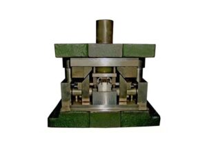
Summary Of 50 Injection Mold Structure Operation Dynamic Diagrams

Molds play an important role in the industry, and a large number of industrialized products are inseparable from molds. Regardless of all walks of life, it is inevitable to deal with molds, so it is very meaningful to be familiar with and understand the structural principles of various common molds.

I have sorted out 50 common mold structure dynamic diagrams sharing for you, which are clear at a glance, which will help you better understand the mold structure and operation process. It is especially suitable for the mold industry practitioners to study, study, and use.

  1. Single parting surface injection mold

Single parting surface injection mold

The single parting surface injection mold has only one parting surface, and the plastic parts and plastics must be taken out on this parting surface. The two sides of the separate molding surface are the movable template and the fixed template, so the single parting surface injection mold is again it is called a two-plate mold.

2. Double parting surface injection mold

2. Double parting surface injection mold

The double parting surface injection mold has two parting surfaces, which are used to take out plastic parts and aggregates. The mold is divided into a movable template, an intermediate plate, and a fixed template by two parting surfaces, so it is called a three-plate injection mold.

The so-called three-plate mold is one more answer plate than the front mold of the two-way return mold. The three-plate mold is usually filled with glue, and the product can be separated from the hopper through two molds. In the so-called picking method.

Generally, the three-plate mold is taken by a manipulator, and the two-plate mold can be taken by a manipulator, which can be taken manually or can be automatically dropped.

3. Mould spring reset mechanism

3.Mould-spring-reset-mechanism

To use the spring force to return the ejector pin is to install the spring directly on the return pin. The structure of this mechanism is simple, but it is necessary to pay attention to the elastic force of the spring to be sufficient, and the spring must be replaced in time when it fails.

If it is not enough to install the spring on the return pin alone, you can directly install a spring between the top plate and the male template to facilitate the return of the top plate.

4. Injection mold with a fixed mold setting and ejection mechanism

4. Injection mold with a fixed mold setting and ejection mechanism

Because the ejection mechanism of the injection molding machine is on the side of the movable mold after the mold is opened, the plastic parts should be kept on the side of the movable mold as much as possible, but sometimes due to the special requirements of the plastic parts or the limitation of the shape, the plastic parts must be left in the fixed mold.

At this time, an ejection mechanism should be set on the side of the fixed mold to eject the plastic part from the fixed mold.

5. Mold secondary launch mechanism

5. Mold secondary launch mechanism

The secondary ejection mechanism is a type of ejection mechanism that can achieve two ejection actions in the mold one after another, and the two ejection actions have a specific sequence in time.

Working principle: When the mold is opened, the pusher plate is pushed away from the core by the spring force to achieve the first demold. The pusher plate is controlled by the limit screw to limit the position, and then the plastic part is removed from the pusher by the push rod The board is ejected to form a secondary demoulding.

6. Mold angle pin side core pulling-mold opening stroke

Mold-angle-pin-side-core-pulling-mold-opening-stroke

The mold opening stroke of the injection molding machine refers to the moving distance between the two clamping plates (templates) of the injection molding machine. The larger the stroke, the larger the mold capacity.

The maximum distance of the template refers to the maximum distance of the stroke, that is, the distance between the two templates when the mold is opened to the maximum.

7. Mold single ejector pin secondary demoulding mechanism-swing block pull plate type

Mold-single-ejector-pin-secondary-demoulding-mechanism-swing-block-pull-plate-type

After parting for a certain distance, the cam pull rod pulls the pusher plate and starts to eject once. When it continues to move, after the bump fixed on the movable mold fixing plate touches the cam pull rod, the cam pull rod rotates and separates from the pusher plate to complete One-time ejection action.

The movable mold continues to move, and the ejection system completes the second demolding action, and the spring resets the cam lever. This structure is reliable in action, but due to the installation of a cam pull rod device on the fixed mold, the size of the mold is increased.

8. The secondary ejection mechanism of the mold single ejector pin spring type

The-secondary-ejection-mechanism-of-the-mold-single-ejector-pin-spring-type

The distance between the backing plate and the push rod fixing plate should be greater than the distance for the second push out. When the mold is opened, after the fixed and movable molds are separated, the ejector rod and backing plate of the injection machine push up the cavity through the pushrod, and the plastic part is ejected from the core to complete the first demolding.

After that, the elastic force of the spring pushes the push rod fixing plate, and the plastic part is ejected from the cavity through the pushrod, and the plastic part is free to fall off from the mold. The method has a simple structure, but the disadvantage is that the action is not reliable, the spring is prone to failure, and needs to be replaced in time.

9. Single ejector pin secondary demoulding mechanism angle pin type

Single-ejector-pin-secondary-demoulding-mechanism-angle-pin-type

When the ejector rod of the injection molding machine pushes the pusher plate, the pusher plate drives the pushrod to move together to make the plastic part separate from the core. At the same time, the slider moves to the center under the action of the inclined guide pin to complete the first Launches.

When the movement is continued, the moving distance of the push rod is greater than the moving distance of the pusher plate due to the action of the oblique guide pin, and the plastic part is separated from the pusher plate to complete the second push.

10. Mold foldable core-pulling-three-dimensional

Mold-foldable-core-pulling-three-dimensional

11. Mold foldable core pulling-plane

Mold-foldable-core-pulling-plane

12. Die oblique guide column lateral parting and core pulling mechanism-slider

Die-oblique-guide-column-lateral-parting-and-core-pulling-mechanism-slider

The lateral parting and core pulling mechanism of the angle pin consists of the inclined guide pin, side core slider, and wedge slider. It is composed of a stopper, slider pull rod, spring, nut, and other parts.

The functions of each part are as follows:

When the mold is opened, the movable mold part moves backward, and the mold opening force drives the side core slider through the angle pin to slide outward in the guide chute of the movable template until the side core slider and the plastic part are completely separated Open, complete the lateral core pulling action.

The plastic part is wrapped on the core, and the moving mold continues to move backward until the ejector pin of the injection machine contacts the mold push plate, the ejection mechanism starts to work, and the pushrod pushes the plastic part out of the core.

Key points: Pull the core side when opening the mold, and push the part after the core is pulled

The mechanism that can pull out and reset the movable core is called the core pulling mechanism.

When the sidewall of the plastic part has through holes, cavities, or bosses, the molded parts must be made laterally movable, otherwise, the plastic part cannot be demolded. The whole mechanism that drives the core slider to move laterally is called the lateral parting and core pulling mechanism.

13. Die Slider Bent Pin Type Lateral Parting and Core Pulling Mechanism-Slider

Die-Slider-Bent-Pin-Type-Lateral-Parting-and-Core-Pulling-Mechanism-Slider-2

The sliding block is an important part of the inclined pin core pulling mechanism. It is equipped with side cores or molding inserts, which are driven by the inclined pin to realize side core pulling or lateral parting.

14. Die bending pin lateral parting and core pulling mechanism-slider

Die-bending-pin-lateral-parting-and-core-pulling-mechanism-slider-3

The bending pin lateral parting and core pulling mechanism is a deformation of the inclined pin lateral parting and core pulling mechanism.

Working principle: It is the same as the oblique pin lateral parting and core pulling mechanism, the difference is that the oblique pin is replaced by a curved pin.

15. Die oblique slider lateral parting and core pulling mechanism-slider

Die-oblique-slider-lateral-parting-and-core-pulling-mechanism-slider-4

Applicable occasions

The side hole or undercut of the plastic part is shallow, and the required core pulling distance is not large but the molding area is large.

Advantages

Simple structure, convenient manufacturing, reliable action, and wide application.

Structural form: slide guide sliding and inclined sliding rod guide sliding

16. Die oblique slider lateral parting and core pulling mechanism-slider

Die-oblique-slider-lateral-parting-and-core-pulling-mechanism-slider-5

17. Side Parting and Core Pulling Mechanism of Die Slant Guide Slot-Slider

Side-Parting-and-Core-Pulling-Mechanism-of-Die-Slant-Guide-Slot-Slider-6

18. The side parting and core pulling mechanism of the inclined ejector rod of the mold-slider

The-side-parting-and-core-pulling-mechanism-of-the-inclined-ejector-rod-of-the-mold-slider-7

19. Mold slider demolding-external thread

Mold-slider-demolding-external-thread

Thread mold manufacturing method There are two types of threads on plastic products: external thread and internal thread. The external thread is usually demolded with a slider, and the internal thread is demolded by the twisting method.

20. The ejector pin of the mold is pushed out and demolded

The-ejector-pin-of-the-mold-is-pushed-out-and-demolded

This mechanism is suitable for deep cylindrical, thin-walled plastic parts that do not allow ejector pin traces, or a small multi-cavity shell (such as button plastic parts). Its characteristics are uniform thrust, smooth demolding, and plastic parts are not easily deformed. It is not suitable for rubber parts with complicated shapes around the parting surface and difficulty in processing the push plate hole.

21. Mold ejector pin launches demoulding-reinforcement

Mold-ejector-pin-launches-demoulding-reinforcement

Selection of the push-out position of the mold ejector pin The pushrod should be located in a place where the plastic part is not easy to be deformed and has high resistance, such as bosses, ribs, and near the core.

22. Mold ejector pin ejects mold release-inclined plane

Mold-ejector-pin-ejects-mold-release-inclined-plane

If the surface of the topped plastic product is inclined, the fixed part should be designed with an anti-rotation structure.

23. The mold is pushed out and ejected from the mold

The-mold-is-pushed-out-and-ejected-from-the-mold

An injection mold push tube ejection stroke control mechanism belongs to the field of injection molds.

A pushing tube is also called a hollow push rod or jacking tube. It is especially suitable for demolding plastic parts with holes in the center such as a circular ring and cylindrical shape. Its advantage is that the push is stable and reliable. The entire periphery pushes the plastic parts. Uniform force, no deformation, no push-out marks, high coaxiality.

But for thin-walled deep-tube plastic parts (wall thickness less than 1.5mm) and soft plastics (such as polyethylene, soft polyvinyl, etc.) plastic parts, because they are easy to deform, it is not easy to eject with a separate push tube, and other products should be used at the same time. Components (such as pushrods) can achieve the desired effect.

24. Mold bar ejection to ejectdemoulding

Mold bar ejection to ejectdemoulding

For flat-shaped maggots with flanges. If the mold is removed by the push plate, the mold will be attached, and the push block release structure can be used. This kind of plastic part sometimes uses a push rod demoulding mechanism, but the plastic parts are easy to deform and have ejection marks on the surface.

25. The mold bar ejection to eject the mold release

The-mold-bar-ejection-to-push-out-the-mold-release

The reset of the push block is realized by the melt pressure in the main channel; the reset rod is installed on the shoulder of the push block, and the structure is simple and compact, but the hole of the reset rod is very close to the cavity, which has a certain impact on the strength of the cavity; the reset rod is fixed On the push rod fixing plate, it is suitable for the situation where the push block size is small and there is no shoulder.

26. Postpone release of mold release

Postpone-release-of-mold-release

27. Mold round pushrod ejection

Mold-round-pushrod-ejection

28. Mold base and insert-C type

Mold-base-and-insert-C-type

Mold core (insert) and template determination. The mold base generally uses standard mold bases and standard accessories, which is very beneficial to shorten the manufacturing cycle and reduce the manufacturing cost.

When the structure is complicated and requires a special parting or ejection mechanism or a lateral parting structure requires a slider, the size of the insert and the formwork and the thickness of each formwork should be adjusted appropriately according to different conditions to ensure the strength of the formwork.

29. The ejection form of the main sprue of the mold

The-ejection-form-of-the-main-sprue-of-the-mold

In general plastic molds, an ejector pin is used to push the main runner aggregate out of the movable mold. The end of the ejector pin is flush with the top of the cold material cavity or less than 0.5-1mm.

30. Two forms of mold main sprue

Two-forms-of-mold-main-sprue

The structure of the main sprue is as follows:

(1) Integral sprue is the simplest form of sprue, which is processed in a fixed template form an integral structure. Its processing is the simplest and is mostly suitable for simple molds.

(2) Combined sprue, if the fixed mold is composed of two templates, the sprue can also be processed separately on the two templates and then combined together. This form is simple, but care must be taken to ensure its coaxially.

(3) The bushing sprue is the most commonly used sprue structure at present. It is embedded in the template in the form of a sprue sleeve and is suitable for all injection molds. This form is convenient for processing, disassembly, and heat treatment.

There are two basic forms of mold sprue pull rods. One is a pull rod in the form of a push rod, and the other is a pull rod that is only suitable for demolding of the push plate. Its typical form is a Z-head pull rod.

31. Mold parting surface-vertical parting surface

Mold parting surface-vertical parting surface

The parting surface should be selected at the largest contour of the plastic part shape.

After the position of the plastic part is determined in the moving and fixed molds, the parting surface should be selected at the largest contour of the plastic part shape, otherwise, the plastic part will not be able to move from the cavity. Get out, this is the most basic principle of choice.

32. Mold parting surface-step parting surface

Mold parting surface-step parting surface

The selection of the parting surface should be conducive to the smooth demolding of the plastic part. Since the ejection device of the injection machine is set on the side of the movable mold, the selection of the parting surface should make the plastic part stay in the movable mold as much as possible after the mold is opened.

On the one hand, this is helpful for setting the ejection mechanism in the movable mold part, otherwise, the setting of the ejection mechanism in the fixed mold will increase the complexity of the mold.

33. Mold parting surface-plane and curved parting surface

Mold parting surface-plane and curved parting surface

The selection of the parting surface should ensure the accuracy requirements of the plastic part. For the size of the plastic part perpendicular to the parting surface, if the size is related to the parting surface, the dimensional accuracy will be expanded due to the parting surface during injection molding. The trend is affected.

The selection of the parting surface should facilitate the processing and manufacturing of the mold. Usually, in the mold design, more straight parting surfaces are selected. But in order to facilitate the manufacture of the mold, a reasonable parting surface should be selected according to the actual situation of the mold.

34. Mold parting surface-horizontal parting surface

Mold parting surface-horizontal parting surface

The selection of the parting surface should meet the appearance quality requirements of the plastic part.

Because the plastic part will inevitably leave traces of overflow and flash at the parting surface, it is best not to set the parting surface outside the bright and smooth plastic part.

The surface or the corners with arcs, so as not to affect the appearance quality of the plastic parts.

35. Mold lever reset

Mold lever reset

After the ejection mechanism finishes ejecting the plastic part, it must return to the initial position for the next cycle. At present, the commonly used reset forms mainly include resetting lever reset and spring reset.

The reset rod is also called the return rod or the reverse ejector rod. The reset rod must be installed on the pushrod fixing plate, and the length of each reset rod must be the same. The end face of the reset rod is often lower than the template plane 0.02 to 0.05mm. There are generally 2 to 4 reset rods, which are located outside the mold cavity and gating system.

Since each time the mold is closed, the end face of the reset rod must collide with the fixed template. To avoid deformation, the end face of the reset rod and the corresponding position of the fixed template in contact with it should be inlaid with quenched inserts.

If the production batch is not large or the precision requirements of the plastic parts are not high, the reset rod can be quenched, and the fixed template may not be quenched. The reset rod sometimes doubles as a guide pin, so the guide element of the demoulding mechanism can be omitted.

If the mold structure allows, try to avoid placing the push rod in the projection range of the side core perpendicular to the mold opening direction.

Make the pushing distance of the push rod smaller than the lowest surface of the sliding core.

36. Change the position of the parting line-example

Change the position of the parting line-example

37. Positioning of the dowel pin

Positioning of the dowel pin

The locating pin is used for closing the upper and lower molds. The clamping pins of the upper and lower molds are large cylindrical or round holes around the mold.

38. Schematic diagram of mold movable inserts

Schematic diagram of mold movable inserts

Movable inserts are irregular mold components especially used for inlay in molds.

Insert is a general term. In the mold, it is an irregular mold accessory specially used for inlaying in the mold and plays the role of fixing the template and filling the space between the template. Inserts can be square, round, or sheet type. 

Like all mold parts, the precision requirements are also very high. Generally, there is no finished product, and it is customized according to the needs of the mold.

39. The influence of the number and position of the mold gate on the weld line

The influence of the number and position of the mold gate on the weld line

The influence of the selection of mold gate on the weld mark, and control the formation of the weld mark.

40. Mold sprue bushing and injection machine gate

Mold sprue bushing and injection machine gate

41. The mold has a cold chute to increase the welding strength

The mold has a cold chute to increase the welding strength

42. Mold air valve bleed -1

Mold air valve bleed -1

Air-entraining is to introduce the air outside the mold into the mold cavity to facilitate the demolding of the plastic part.

For some large deep-shell plastic parts, the gas in the cavity is completely removed after injection molding, and a vacuum is basically formed between the surface of the plastic part and the cavity, which sucks the plastic part and makes it difficult to demold.

If demolding is forced, the plastic part is likely to be damaged. For this reason, an air-entraining system must be designed to introduce air between the plastic part and the cavity.

When the melt is injected into the cavity and fills the cavity, the valve is pressed tightly due to the pressure of the plastic part, making it in a closed state.

When the mold is opened, the push plate pushes the plastic part out, and a vacuum is formed between the plastic part and the core, and the check valve is sucked open. At this time, air can be introduced and the plastic part can be demolded smoothly.

Backlash air-entraining. When the insert or core is in interference fit with other molded parts, it is difficult for air to enter the cavity. If the fit-gap increases, the position accuracy of the insert will decrease.

43. Mold air valve bleed -2

Mold air valve bleed -2

44. Mold valve ejection mechanism

Mold valve ejection mechanism

Pneumatic ejection mechanism: Use compressed air to blow out plastic parts through tiny ejection holes or air valves in the cavity. (2) According to the type of the push component, it is divided into push rod push, push tube push, push plate push, movable insert or die push, etc.

45. Mold ejector pin release structure form

Mold ejector pin release structure form

There are three demoulding structures commonly used in injection molds: ejector pin, ejector sleeve (sleeve pin), and inclined top slider ejection. The main parts are the ejector inner, ejector fixed container, and push plate.

Mandrel demoulding is often used for demoulding products with general structure;

Push plate demolding is often used for demolding thin-walled products. The main parts are ejector pin, ejector sleeve, and ejector plate;

The demoulding form of the inclined top slider is often used for demoulding products with a concave-convex structure on the side. The main parts are the ejector pin, ejector sleeve, and ejector plate;

46. Mold ejector plate release structure

Mold ejector plate release structure

47. Mold ejector plate release structure form

Mold ejector plate release structure form

48. The matching form of mold ejector plate and core

The matching form of mold ejector plate and core

49. Mold ejector pin eject mechanism form

Mold ejector pin eject mechanism form

In each cycle of injection molding, the plastic part must be accurately ejected from the mold cavity or core. The device that completes the ejection of the plastic part is called the ejection mechanism, also often called the ejection mechanism. The ejection mechanism is generally composed of three components: ejection, reset, and guidance.

50. Mold ejector pin eject mechanism

Mold ejector pin eject mechanism

The function of the push-out mechanism is to push the molded plastic part out of the row cavity, and its form is divided according to its structure: push rod push mechanism, push plate push mechanism, row cavity push mechanism, combined push mechanism. According to the power source: manual launch, motor launch, hydraulic launch, etc.

Please think about the following questions.

  1. What is the role of the lateral parting core pulling mechanism in the mold?
  2. How many types of mold lateral parting core-pulling mechanisms are there?
  3. What are the main advantages and disadvantages of the lateral parting core-pulling mechanism of the mold?
  4. How to calculate the extraction force and the extraction distance? What is the basis?
  5. How to calculate the diagonal pin-straight warp, diagonal pin length, and mold opening stroke?
  6. What are the structural elements of the oblique pin lateral parting core-pulling mechanism?
  7. What issues should be paid attention to when designing?
  8. Under what circumstances need to use the first reset mechanism?
  9. Analyze the structural characteristics of the four use forms of the inclined pin lateral parting core-pulling mechanism, and which structure is the simplest?
  10. What is the difference between the mold slider guide sliding and the inclined slider side parting core pulling mechanism of the inclined rod guide sliding?
  11. What are the structural characteristics that should be paid attention to when designing the side parting core-pulling mechanism of the inclined sliding block guided by the mold slider and the inclined rod?
  12. What occasions are the mold slide guide sliding and the inclined slide guided sliding side part core pulling mechanism of the inclined slider suitable for?
  13. What are the characteristics of hydraulic core pulling?
  14. What are the characteristics of rack and pinion core pulling?

You may also be interested in the below articles:

What Is Cold Forging?

What Is Blow Molding?

What Is An Overmold?

Share: