Description
What are Locating Rings?
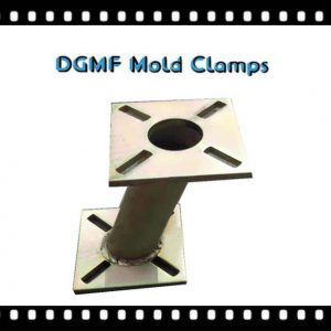
A locating ring‘s basic job function is to locate or align the orifice of the hot or cold sprue with the through-hole in the machine’s stationary platen. The sprue orifice is usually in the center of a sprue bushing, and the locating ring aligns the bushing to the center of the platen. Locating Rings – Fixing Rings / Locating rings for pedestal bearing housings.

The locating ring is usually in the center of the mold. Sometimes, though, the locating ring is offset by several inches to reduce the size of the mold base, such as with a single-cavity, edge-gated part.
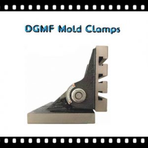
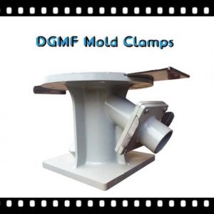
Locating rings are used in split Plummer block housings to locate the shaft axially in both directions.
The Mold Components Locating Rings Drawings and Locating Rings Specifications
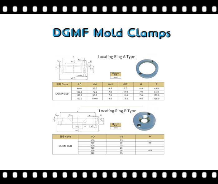
mold components Locating Ring drawing
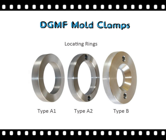
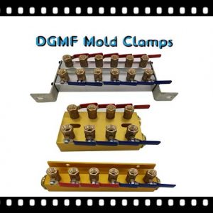
There are three common types of locating rings.
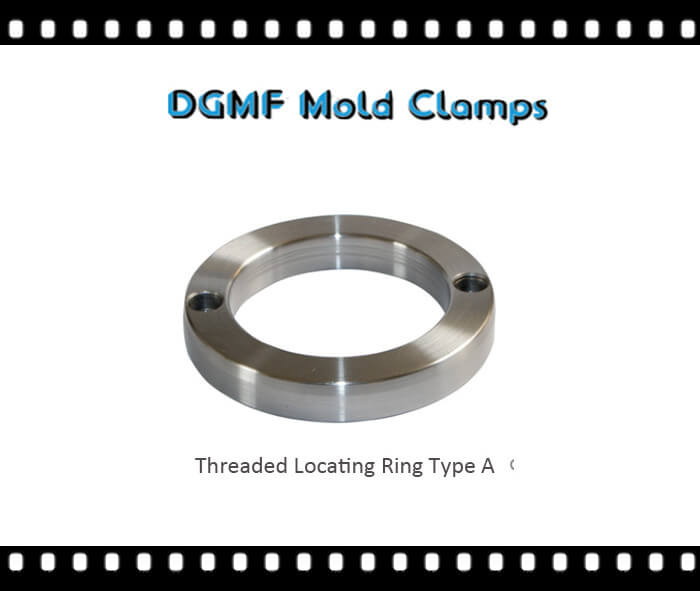
Type A locating ring
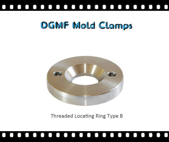
Type B locating ring
Type A without hole locating ring

Positioning locating ring design requirements
The positioning of locating ring is a structural part that plays a role in positioning when the mold is installed on the injection molding machine. The diameter of the domestically-made positioning ring is 0.2~0.4mm smaller than the panel hole of the injection molding machine. Generally, large molds need to press the sprue sleeve with a positioning ring to prevent the fixing screw from being broken by the reaction force during injection molding.
Sprue bushing
① Design requirements for sprue bushing.
a. The inner hole size of the sprue bushing is required to be the same as that of the sprue channel. It is designed to be conical, and the taper angle is generally 1.5°~4°.
b. The SR and the diameter of the contact with the nozzle are both greater than the nozzle radius by 0.5~1mm.
c. The surface of the main runner should be as smooth as possible, and the heat treatment hardness should be 52~55HRC.
d. The main runner design requires the length to be as short as possible, not too long, preferably around 60mm (the longest is 80mm, the shortest is 40mm).
e. The outer diameter of the sprue bushing and the template hole is matched with H7/j7.
f. The sprue bushing design with an uneven head requires a rotation stop device.
Pull rod 5 t;
① The main runner pull rod of the second plate mold.
② The tie rod of the point gate of the three-plate mold branch runner
Reset lever
The reset rod and the movable template are in clearance fit, the fit tolerance is H7/f6, and the fit length is 1.5 times the diameter of the reset rod, and the other places are kept away from the air. When the length of the template exceeds 600mm, two more reset rods should be added.
Slide retainer
The function of the Slide retainer is to prevent damage to the parts when the mold is ejected. When using the standard formwork, avoid the shim and the limit post being too high and make the ejector rod too long, otherwise, the ejector rod strength will be weaker.
Support pillar
The support pillar is mainly used to bear the bulging force of the melt on the movable template during the injection molding of the mold, to prevent the movable template from deforming under the action of the injection force, so as to improve the rigidity of the mold. The requirements for support pillars are as follows.
① The shape of the support pillar is generally cylindrical, the same as the shim. The material is 45 steel or yellow steel S50C, and the hardness shall not be higher than 5° or the same as the shim.
② The position of the support pillar should be at the place where the mold is stressed. Do not put the support pillar next to the mold frame.
③ The height is the same as the nominal size of the shim, and its tolerance is +0.063~+0.035mm. The support pillar is fastened on the bottom plate of the movable mold by screws.
④ The number of support pillars should be appropriate, not too many or too few. Too much-wasted material will increase the cost of the mold, and at the same time weaken the strength of the ejector pin fixing plate 4 and the top plate 5, and too little will make it difficult to ensure the rigidity of the mold. The number of support pillars can be determined by calculating the total area of the mold that needs to be supported.


Reviews
There are no reviews yet.