185 injection moulding die design experiences are precious information! Worth collecting.
The 1 to 10 injection moulding die design experiences
- The height of the slider guide should be at least 1/3 of the slider height to ensure the stability of the slider and smooth sliding.
- Sliding friction positions attention to open lubrication groove, in order to prevent the flow of lubricant, should not open the groove into “open”, but should be closed, generally can use a single blade in the milling machine directly milling out.
- The cavity of the fixed die is generally cut by line for the small die, which can improve the accuracy of the mold; while the cavity of the larger die is generally processed by milling, pay attention to its verticality when processing, and in order to prevent the assembly, the die is not in place, the surrounding of the mold frame should be milled with a milling cutter 0.2 deep.
- The interpenetration of the inlet and the mold kernel, the die kernel, and the die kernel and the mold frame should generally add a slope of 1° to prevent bruising when assembling.
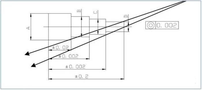
- The tolerance of the length of the inlet part is -0.02, the tolerance of the size is -0.10, and the tolerance of the corresponding inlet of the die insert is +0.02.
- The tolerance from the bottom to the C corner part of the entry with the C corner is +0.01, to prevent the running edge.
- Use NAK80 material for the main part of the body mold, SKH9, SKH51 (material treatment: chambering treatment, or not) for the inlet, tip, etc., or use VIKING material if necessary.
- After drawing the parts, the position and size of the slider should be set first to prevent interference and insufficient strength, and then set the mold kernel inch method.
- The tolerance of the size of the insert is set to -0.01, and the tolerance of the corresponding insert hole on the die is +0.01.
- The sharp corner part of the square hole of the wire cutting on the mold kernel is R0.20 over, and the corresponding inlet part is also R0.20, in order to correspond to the influence of the wire diameter during the wire cutting, and at the same time, it can prevent the sharp corner part from wearing out and producing the beneficial edge.
The 11 to 20 injection moulding die design experiences
- The small pit corresponding to the positioning bead is generally a conical hole with a base diameter of φ3 and an angle of 90°-120°.
- Fixed side of the extraction angle should be greater than the movable side, in order to leave the shape to stay on the movable side; and can prevent the deformation of the parts, especially thin-walled, long pieces of easily deformed parts, the fixed side of the uneven pull on it is easy to make the parts warp, or stay on the fixed side.
- For the side of the core force and the parts of strict precision requirements of the parts, it is best to use the second core structure.
- The slope of the oblique tip + 2 ° = the slope of the compression block (generally 18 ° or 20 ° or 22 °).
- When the mold is assembled, the following habits should be developed.
Clean the surface of the die kernel, die cavity, inlet, runner plate, and parting surface with the air gun.
Use oil stone to polish the surface of the die kernel, cavity, inlet, and parting surface before assembling, so that the assembly will be smooth.
Pay attention to clearing the corners to prevent interference and bruising.
Before assembling, you should consider how to do the work later.
- The side compression block of the large mold insert should be designed to lock the bottom 0.5-1.0mm on the parting surface to prevent interference.
- PC+GF20 shrinkage rate 3/100018. POM shrinkage rate is normally 20/1000, but sometimes local will reach 30/1000.
- In order to prevent the submerged gate from scratching the part when the part is ejected, add a wedge-shaped block 2-4mm away from the submerged gate in the runner, about half the height of the runner, with the angle of 10° on one side, for breaking the gate when the part is ejected.
19 Mainstream channel pulling material well, using 8-10mm deep, angle of 10° on one side, top diameter is the width of the runner inverted cone; the advantage of this is to prevent the single side grinding into the wedge shape of the pulling material in the ejection hooked runner, resulting in the poor release.
- There are two kinds of openers and closers.
Made of rubber, relying on the screw in the center to adjust the amount of deformation to adjust the tension.
Made of spring steel.
The role of both: delay the mold opening time of the movable side and fixed side, applied to small water mouth mold.
The 21 to 30 injection moulding die design experiences
- In order to make sure that the ejector pin and tilt pin of the mold are reset, some molds are equipped with an early return mechanism (female on board 108 and male on board 102, the male is similar to the ejector pin, the bottom is blocked with headless screws, generally two are arranged) or micro switch (between boards 108 and 109 [with electrical components]).
- Considering the length of the screw when clamping the mold on the injection molding machine, it is necessary to pay attention to the thickness of the upper and lower fixing plates, and the four corners should be milled lower if necessary.
- The molding end of the bevel pin has a straight section, generally 4-6mm long, in order to slide smoothly between 107 and 108 plates when ejecting the bevel pin should be inverted 0.5mm-1mm R angle at the bottom.
- The design of the slope of the die pulling needs to consider the degree of bite to avoid the appearance of strains. For some protruding parts, the cross-section will be bigger after considering the nibbling, so the actual processing should be 0.02-0.03 smaller on one side.
- Considering that the fixed side and the movable side will form a broken difference, the fixed side is smaller than the movable side by 0.03-0.05 on one side.
- In molds with sliders, it is sometimes necessary to open a groove on the slider on the sliding block against the pressing block on the sliding block; in addition, if it does not affect the forming, it is more efficient to open a groove on the upper surface of the template than to open a groove on the bottom of the slider.
- The parting surface should not be chosen in the position where the surface is required.
- The shrinkage rate of the added fiber is 1-2 thousandths in the flow direction, and large perpendicular to the flow direction; the opposite is true for the non-added fiber.
- The shrinkage rate of the tooth top circle is smaller than that of the tooth root circle by 1-2 thousandths.
- After using the mold for a period of time, it is necessary to carry out type repair, repairing the process of mold kernel, try not to use oil stone, because repeated use of oil stone will make the mold deformation; it is better to use chipped cork or soft bamboo chopsticks.
The 31 to 40 injection moulding die design experiences
- In the mold with the slider, four support crutches should be added between #102 and #103 plates.
- When forming parts with insert and mold kernel inside, consider the second core extraction mechanism to avoid the difficulty of demoulding and damage to the parts.
If the insert is on the fixed side or on the slider, the insert is often withdrawn first.
If the inlet is on the movable side, and the fixed side is broken, the sink hole of the inlet can be made deeper, so that the part can be ejected first when ejecting, and then the inlet can be taken off. If it is not broken, the part should be taken off first, then the corresponding mold structure should be changed.
- If the surface between the fixed side and the movable side is not perpendicular to the mold opening direction, it should be designed as a beveled surface to reduce the possibility of forming a flying edge due to friction.
It should be designed with a positive tolerance of +0.02 in the length direction, but it should be noted that when the fixed side and the movable side have a release slope.
However, it should be noted that when the fixed side and the movable side have a release slope, it should be carefully considered that because the fixed side and the movable side have the opposite direction of the release slope, a joint mark will be formed at the slope against the broken part that does not match the original design of the part.
- When the fixed side needs to nibble, the shape size of the fixed side should be small 0.03-0.05mm on one side of the design according to the degree of nibbling.
- The polishing of electrode is generally done with 1000 sandpaper, but the appearance electrode needs to be polished with 1200 or more sandpaper; the polishing of mold kernel is done with 1500, but those requiring mirror surface should be done with 3000 sandpaper, and finally polished with drilling plaster and degreasing cotton. When the matching into the sub, first with 400 sandpaper, then 800 sandpaper, but the Japanese mold into the sub seems to have used 1000-1200 sandpaper for polishing.
- After the plastic gears are formed, the measurement of gear parameters are mainly tooth top circle and cross tooth thickness, if the two gears are too tight, or too loose will affect the driveability; cross tooth thickness measurement has a special measuring instrument.
- In the injection moulding die design, if the flesh thickness of the parts is not uniform, and the gates of the parts are evenly distributed, the phenomenon of uneven pouring will be easily produced.
- Gears made of PC+30GF, although better in terms of forming size, generally can be four pieces in one mold, but its rigidity, wear resistance, etc. is not as good as PBT+GF30, therefore, although PBT in terms of forming size is not easy to control, only two pieces in one mold, manufacturers like Olympus who focus on quality, in front of quality and cost, still choose the quality.
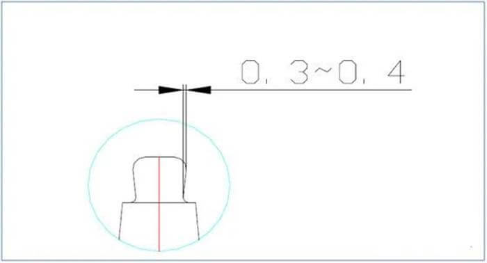
- In the injection moulding die design, in order not to affect the use of parts, often need to recess a piece in the surface of the parts, so that the gate shear residue is lower than the surface of the parts, the depth of the recess to meet the premise of the gate residue is lower than the surface of the parts, the shallower the better, generally 0.3-0.5mm, too deep will affect the size of the molding.
- In order to improve the filling performance at the distal end of the part from the gate, it is possible to open an escape groove in these parts to increase the entry; this should be considered especially before designing, and when setting the structure, there should be a concept that the pressure and temperature of each part of the fluid flowing in the mold cavity should be constant as much as possible.
The 41 to 50 injection moulding die design experiences
- For molds with thin flesh and difficult forming, such as Wang Feng’s 0001 and 0002, the forming performance can be improved by increasing the point gate, but not the bigger the better. Therefore, the point gate should be ¢0.5-1.2mm.
- In EDM, there is a direct connection between the discharge gap and processing accuracy (generally 3:1).
- The slope of the compression block of the large mold kernel is 1°, 3°, 5°45. In order to facilitate the ejection of the slanted pin, the slanted pin should be designed to be shorter than normal by 0.1-0.3mm, i.e. the meat of the part is thicker than normal by 0.1-0.3mm.
- When making injection moulding die design should first consider the processing of the parts, try to avoid the use of electrical discharge and wire cutting, but try to consider the use of milling and grinding machines, because of the processing cost, processing accuracy, and processing time, the former is not as good as the latter, although the accuracy of slow wire cutting is good.
- The injection moulding die design should avoid a simple shape, but also need a large area of the plane discharge, both time-consuming, precision, and difficult to ensure, and aggravating the clamp workload of the clamp.
- The injection moulding die design should try to avoid the step-shaped and need to face and face each other to fit the upper and lower injection moulding die design, which is often difficult to process.
- The disadvantage of ultrasonic polishing is that it is easy to make the mold surface shape distorted because of inaccurate hand feeling.
- The mass production requirement of the mold is 10000-15000/month, and the material of the die kernel is NAK55.
- A good injection molding machine can adjust the parameters to perform more than 5 stages of injection, such as the first stage to fill the runner; the second stage to fill one-third of the part; the third stage to fill one-half of the part ……, etc. Thus, the problems in injection molding can be solved by analyzing the part-filling situation in these cases.
- For some parts that are difficult to mold, have surface requirements, or some parts that are difficult to reach the required size in the first few mold trials, consider using multi-stage injection molding during the mold trials.
The 51 to 60 injection moulding die design experiences
- The cavity number of the mold is determined by the molding cost of a single part, the average mold-making cost per part, the precision requirement of the part, the difficulty of mold making, etc.
- Molding corrosive resin is the mold material to choose corrosion-resistant materials, or in the mold surface for anti-corrosion treatment; molding resin containing glass fiber and other high-strength filling materials, mold parts must have the corresponding hardness.
- The distance of the water pipe from the mold kernel should be more than 4mm.
- If it is predicted that the parts are difficult to be molded and the molding pressure needs to be increased, the injection moulding die design should consider the strength of the mold, increase the strength of the mold kernel, increase the support column, and pay attention to the tolerance between the laminating surfaces.
- Forced release mechanism should not be considered in precision injection moulding die design, otherwise, it will have a great impact on the mass production, part accuracy, and even part surface of the mold.
- In injection moulding die design, from the cost and manufacturing point of view, try to avoid the slider and tilt tip mechanism.
- If there are only 15-20 pieces of mold kernel left after the milling machine, and two to four pieces of one mold, then even the electrode with a clear tip is generally one coarse and one fine.
- The rough electrode of the complex surface electrode should be reserved at 0.06 in the X and Y direction and 0.07 or more in the Z direction, and then finish with the fine electrode.
- Special attention should be paid to the discharge of sharp angle, semi-circle, and hemisphere electrodes.
- The opening stroke of the small water spout mold is determined as follows.
101A plate and 102 plates off runner stroke is calculated as follows: runner length + robot (40-60mm);
102 plate and 103 plates off part stroke are calculated as part + manipulator (70mm).
The 61 to 70 injection moulding die design experiences
- For parts that are difficult to take out during mold assembly, such as pressure blocks, runner plates with small spouts, mold kernels, etc., it is necessary to drill holes for lifting screws; however, sometimes, for the sake of simplicity, the two clamping screw holes on the opposite corners can be drilled through and tapped through to screw the lifting screws.
- require good concentricity but can not be done at the same time in the fixed side or movable side of the mold, if the size of the mold kernel allows, the fixed side and movable side should be designed with a male and a female conical guide mechanism, in order to ensure the concentricity of the position when forming. For example, 9018, 9026, 0004, and 0032 roller molds are added with the #251 inlet.
- For molds with a large molding quantity, consider the selection of the material of mold frame (P20 can be considered) and slider (P20), and at the same time, you can install a resistant template on the side slick block.
- When processing mold parts with thicknesses less than 5mm and lengths more than 50 by grinding machine or milling machine, i.e. the ratio of length to thickness is more than 10, such as slanting tip, we should pay attention to the deformation problem when processing.
Sometimes the mold cavity used to place the die insert is too deep, and it is necessary to open the cooling ring, if you directly use the knife to process the cooling slot in the mold cavity, the knife is often not long enough, then you can consider opening the cooling slot at the bottom of the die insert, but the point to note is that the cooling slot in the middle of the cylinder should be slightly larger than the inner diameter of the cooling ring so that the cooling ring is not easy to fall out of the cooling slot.
(Note, because the cooling water is from the inside, the injection moulding die design should let the cooling ring inner diameter and close to the mold wall; if the cooling water is from the outside, the injection moulding die design should let the cooling ring outer diameter and close to the mold wall, this point must not be reversed, otherwise it will cause oil leakage)
- The temperature of the cooling water outlet and inlet should be as small as possible, within 5°C for general molds and within 2°C for precision molds.
- The center distance between waterways is generally 3~5 times the waterway diameter, and the distance between the outer circumference of the waterway and the surface of the mold cavity is generally 10-15mm.
- For molding resins with large shrinkage such as polyethylene (PE), a cooling circuit must be set in the direction of the large shrinkage of the product.
- When there are several groups of cooling circuits on the mold, the cooling water should be passed into the part close to the mainstream first.
- The material of the slant tip is generally required to be hard (SKH9 or STAVAX), and to improve the mass production, add a wear plate (SKS3 material) between the bottom of the slant tip (#106 ejector plate and #107 ejector fixing plate) with the same thickness as the bottom of the ejector.
The 71 to 80 injection moulding die design experiences
- Generally, if the dent amount of the product is less than 3%, almost all of them can be used for forced demoulding, if it exceeds a certain range, the finished product will be scratched or even damaged during demoulding. The amount of depression is also easy to material, soft materials such as PP, and NYLON can reach 5%, while PC, POM, etc. can only be between 2.5~3%.
- The safety distance of the slider is generally 1.5~5mm.
- The root or top part of the plastic thread should have a small plane (about 0.8mm), in order to make it easy to take off the mold after molding, and not easy to hurt the surface of the threaded part.
- The tolerance of the spacer is generally +0.1mm, if the pressure of the mold is large, it is necessary to add the support column, the tolerance of the support column is generally +0.02~0.03mm, which means that the group is 0.02~0.03mm thicker than the spacer.
The reason for this consideration is that the surface of the support column (S45C or S55C) is hardened than the template, and the template will be concave after use for a period of time to compensate for the tolerance.
If the support pillar is 0.1mm thinner than the spacer, the deformation of the #103 plate during injection will be magnified on the die kernel, resulting in more than 0.1mm of bending and thus burr.
- PD613 (better than SKD11), PD555 (better than SUS 420 J2) and NAK 101 (better than SKD11) have a maximum deformation of 0.065/50 for heat treatment, which has high wear resistance, high corrosion resistance, and high mirror finish, and is suitable for processing precision molds.
- The exhaust slot is often opened around the parting surface and runner, and the outer edge of the exhaust slot for general molds is generally 0.5mm deep and 0.02mm on the side of the part; while the outer edge of the exhaust slot for precision molds such as the front and rear cover body of the object camera is generally 0.07-0.1mm deep and 0.007-0.01mm on the side of the part.
- To ensure that the movable side and the fixed side fit well, the parting surface is generally 0.02mm higher than the template; and often in the four corners of #103 milling C10-20 deep 0. 5-1 notch to ensure that #102 and #103 do not interfere.
- Like polyacetal (polyacetal) finished size tolerance is ± 0.2% or so, and the number of die cavities increased by 1 tolerance of about 5%. 8 cavities are increased by 1.4 times, up to ± 0.28%.
- In grinding machines, grooves of 0.5 mm can be ground.
- The surface of the return trip is hard only about 0.5mm thick, and the inside is soft.
The 81 to 90 injection moulding die design experiences
- When finishing a flat surface, STEP generally takes 2/3~4/5 of the tool diameter, and the tool travels slowly.
- The tolerance of the slider slot is -0.01 and +0.01.
- Before injection moulding die design, it is very necessary to cooperate with customers on drawing surface (determination of parting surface, determination of ejector position, disposal of inverted groove, location and shape of a gate, the relationship between flesh thickness and shrinkage, further confirmation of tolerance size, etc.), which is very necessary to further understand customers’ injection moulding die design intention and increase the injection moulding die design hit rate, which is the first concept that designers should establish, and designers should not make their own ideas.
- Hot runners are generally suitable for plastic molds with mass production of 240,000 pieces or more.
- For molds like 9029, 0031, etc. with submerged gate, the straight end of the inlet is often round or flat, and then the round or flat ejector is used, but because the ejector is small and the inlet is long, if there is no release slope at the inlet, poor ejection or breaking of the ejector will often occur when the part is ejected. Ejecting.
- The mold with a large runner, the part which plays the role of cold material should be lengthened accordingly.
- Large molds should be considered in the injection moulding die design of the exhaust slot design, should not be specified after the mold test, according to experience, generally around the mold with a milling cutter or grinder (according to the mold accuracy needs to be determined), processing a week of shallow groove, the depth is less than the overflow edge of the plastic value.
- For the inlet with a C corner, if the C corner part is exactly connected with the die kernel, the length tolerance from the bottom of the inlet to the C corner should be +0.05 in order to prevent the appearance of burr on the part.
- The roughness of mold surface in electrical discharge processing is 7um for general requirements, 4um for the general surface in precision mold, and 2um for mold surface with high appearance requirements.
- The ordering of mold material should be generally 3~5mm larger than the required maximum size.
The 91 to 100 injection moulding die design experiences
- The fitting part of the slider and the die should generally be designed with a slope of 2-3° on one side, which can avoid wear and tear and facilitate pre-pressure.
- The thickness of the coating is generally 0.02~0.03mm on one side, and the polishing amount of the mold is generally .02~0.03mm on one side, which must be considered in the selection of the fit size of the product design and injection moulding die design.
- It is very important for the pincer to match the technique of inserting into the sub, and it is best for the sub to flow slowly, and there should be no loose feeling when the sub is inserted into the cavity at 1/4 depth.
- In molding lenses, high-precision gears, and other precision parts, in order to improve the accuracy of the parts, it is very important to maintain high rigidity of the mold, for this reason, except for #102, #103 other mold parts (material S45C, S55C) often need heat treatment to 45 ° HRC; #102, #103 does not need heat treatment, because the mold kernel part is often higher than the template.
- The molding lenses often need to use YAG-250 (powder metallurgical steel, very pure, produced in Datong steel) mold material, heat treatment to 56 ± 1 ° HRC.
- Sometimes the surface of the mold has some small round dents that need to be polish, in the premise of the conventional method is difficult to solve, sometimes using fiber oil stone (very expensive), sometimes using a simple method, the toothpick clip on the small rocker drill to 6000-10000 rpm, with a light hand to support the mold kernel, dipped in drilling plaster, the part to be polished gently to touch the toothpick to polish.
- General parts of the ejector pin escape meat depth of 0.1 (tolerance of 0 ~ +0.02), precision forming is 0.03 (tolerance of 0 ~ +0.01), in this case on the ejector pin fixed plate (upper ejector plate), ejector pin pad (lower ejector plate) and used to fix the ejector pin escape hole depth, left and right two support blocks, movable side template, movable side die kernel, the length of the ejector pin itself against the position and its total length have Very strict requirements, must be strictly implemented according to the injection moulding die design requirements.
- The order of checking the parts that have been formed is: whether the surface is burnt, flow marks, whether the side walls are strained, whether the filling is sufficient, whether there are burrs at the position of the parting line and leaning broken line, whether there is shrinkage at the opposite side of the meat thickness, whether there are ejector marks on the opposite side of the ejector pin, and whether the depth of the ejector pin escaping meat is reasonable.
- with push plate ejector type mold, if for a mold of multiple pieces, fixed side and movable side also should not be divided into multiple pieces, but to use the overall mold kernel injection moulding die design is appropriate, in order to facilitate the ejector balance.
- For polishing, #5000~#8000 of drilling plaster can achieve the mirror effect.
The 101 to 110 injection moulding die design experiences
- The circular runout of reamer processing is 0.05mm.
102.YKMA-0058 (Oita Canon front cover) screw thread calculation steps.
The main parameter of screw pressure: M41×0.75 (pitch P=0.75, large diameter D=41, middle diameter D2=D-0.649519×P, small diameter D1=D-1.082532×P, action height H1=0.541266×P), and the shrinkage rate of the part is S=1.0058.
Therefore, the pitch of die kernel p1=0.75×S, large diameter d1=41×S, middle diameter D2= d1-0.649519×p1, small diameter D1= d1-1.082532×p1, and action height H1=0.541266×p1.
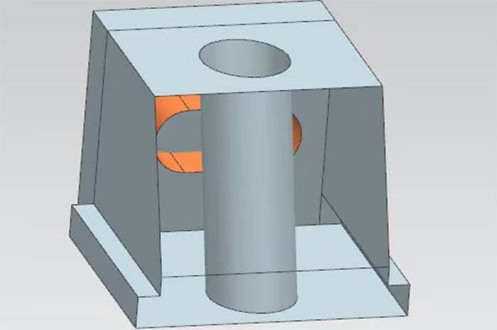
- EP should also escape flesh in the die kernel to reduce friction, as shown in the figure.
- The spring on the small pulley is generally chosen blue (light load) TL type to ensure sufficient elasticity.
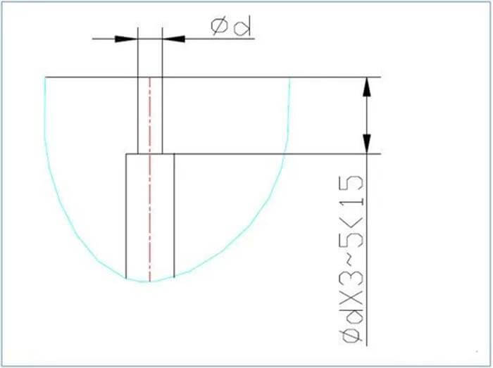
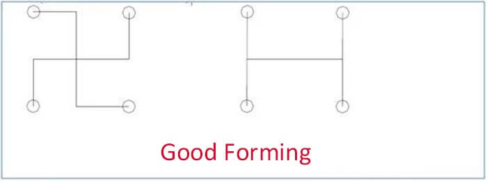
- The pulling material pin generally choose RLRT type, to ensure the following figure inch method. 101 plate on the over hole large 0.2 (bilateral), not marked tolerance. In order to ensure coaxiality, 101 board and 101A board pulling pinhole, irrigation nozzle hole grouping line cutting, in the opening of the mold (101 and 101A pulling apart), so as not to pull off.
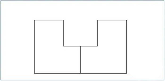
- The icon structure is often designed in the following way to avoid bad air escape during processing.
- The material such as fiber very wears and tears to the die kernel, some easy-to-wear parts should be inserted as much as possible.
- For a mold a large mold, in the non-interference and can not be symmetrically arranged, the support column can be asymmetrically distributed, and more than two pieces according to the situation can also be asymmetrically arranged.
- A set of successful molds, a good designer, often in small, details to show. Micro switch, type open prevent block necessary.
110.QF-TE: heating (burn-in)-tempering.
The 111 to 120 injection moulding die design experiences
- The election of forming machine forming tonnage is determined by forming area, closing force, mold size, and type emperor force.
- Point gate often has the following two forms, fleeing flesh depth B is decided by the material, angle A, and other factors, often 0.5~0.6. ABS, PC materials, and fleeing flesh depth is slightly larger.
- PPE material is suitable for mold temperatures around 60℃, and LCP material is better for forming, it can form 0.14 thick plastic products. The following figure parts.
- Three plate model opening measurement: PL1=scrap length (vertical distance) +10 (robotic take) PL1=gouge mouth to gate length (relative distance) +15 (automatic take down) PL2=A+2~3MM
- For large parts or parts with the required appearance, cooling of the mold kernel is often used, sometimes the mold kernel is cooled at the same time as the template, and even the slider and slant pin will open cooling holes. The lens mold cooling circuit is well-shaped.
For some large molds, such as body, front, and rear cover, and mirror barrel molds (YKMA-1116), 101 and 101A also have water holes for heating to maintain a constant temperature and smooth mold opening movement.
- There is a correlation between the point gate runner and the gate.
- The human error is generally 2umm when testing, when measuring a micrometer, it is appropriate to make 3 sounds when contacting the parts, and the measuring temperature is 22℃+0.5℃.
- mirror mold is generally used in the form of ejected into the sub, the majority of its # 301 on a sub into the need for two tie rods, so into the ejected unbalanced, it is easy to strain into the sub, especially the Sundance sub. For example, in 1024,1141, 104 plates are equipped with a guide bushing, and screws are used to connect the inlet and guide column to 107 plates by a round guide block, and guide movement is made in the guide bushing so that the mass production will be smoother.
PSF material is not easy to generate static electricity, but the price is 2-3 times of PC, so the high-grade products use PSF, and general products use PC.
- The processing order of the mold is:
The bump is not processed first, and the plane is nibbled.
Then, check the flatness of the plane, and repair the mold until it is OK.
Finally, all the bumps are processed, where the height of the bumps on the part should be 0.03-0.05mm lower than the two bars on the side, which should be proposed to the customer during the punching.
After that, polish the bumps, which should be done under 30-50 times magnification. (Usually, polishing is also best to polish under a 5 times magnification), polishing before the machining (milling out with a machining center, but not with electrical discharge, so as not to bump size uneven) margin should be left about 0.03mm for polishing.
The 121 to 130 injection moulding die design experiences
- mirror polishing up to 0.05um, polishing should be reserved before 0.03, high precision requirements must be reserved more, in order to prepare for the next time there is the amount of type repair (with machine polishing to be more uniform).
- The submerged gate should be opened on the slope, not on the plane, in order to prevent the direct impact on the mold kernel and scorch marks on the part when feeding the rubber.
- Countermeasures when scorch marks appear at the part gate: lower the pressure and lower the injection speed to reduce the material shear.
- In the knowledge of parts of the diagram, with coloring or labeling surface height, the benchmark requirements as far as possible unified, the benchmark for 0.00, the benchmark above the “+”, the benchmark below the “-“, general surface labeling main view and top view can be, but for the body and other complex But for complex drawings such as the body, should be marked six sides.
There are three types of 3-dimensional measuring heads: 160. The thin part of the cutting edge is easy to break when forming pressure is high, and it is even easier to break when plastic and glass fiber are added.
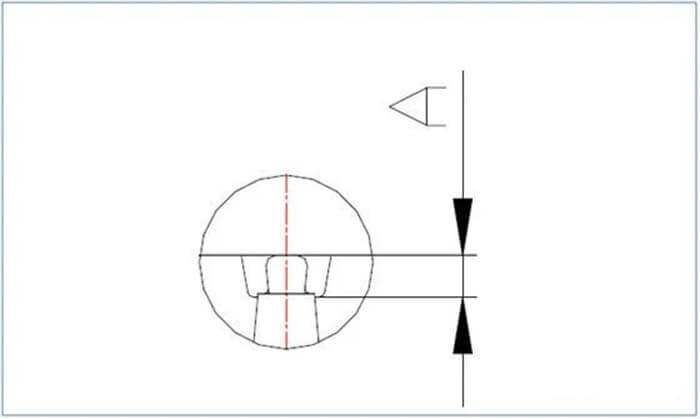
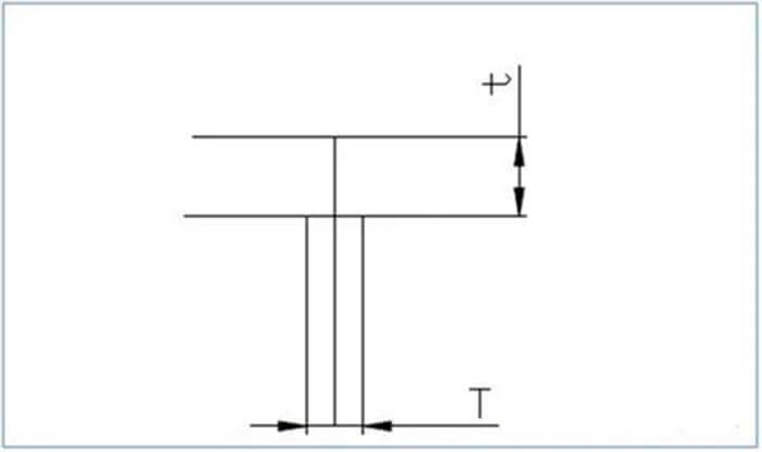
- When forming the part as shown below, T=2/3t, when there is an appearance (fine nibble), T=1/2t, the part is not easy to shrink.
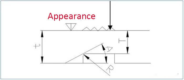
127. When forming the parts as shown below, T>2/3t, the appearance is not easy to produce luster, and the smaller the angle A (30°) or R, the less easy it to produce luster, because this will not make the resin flow backward, resulting in a different luster.
- For the following parts, the point gate distribution should meet: l / t=60~70 (even 100 is OK) for the material with good flow, l is the distance from the point gate to the farthest point, t is the average flesh thickness, l / t=40~50 when it contains 20% glass fiber, l / t=40~50 when it is not normal flesh thickness.
- When the material flows, there are two kinds of materials: crystalline, with large post-acquisition and strong water absorption, such as POM, PBT, and PP for mirror barrel, which are stable only after 48H measurement; non-crystalline, such as ABS and PC.
- When the tolerance of 3D inching is one-way tolerance, we should check with the customer and try to adjust it to two-way tolerance.
For large area thin parts to ensure the forming thickness, use additional gates.
Sometimes the surface can not throw too light, especially for the mirror surface, it will stick to the poor release, # 5000 will occur vacuum condensation, can throw some more coarse.
Do optical lens material, steel should contain more than 15% nickel.
The 131 to 140 injection moulding die design experiences
131.STAVAX is divided into three grades: general grade, MS grade, ES grade (optical mirror)
132.SKD61 is divided into two grades: general grade and forged grade, which have no directionality and good performance.
- ZDC2 aluminum fiber alloy is used for camera tripod screws, the front of the camera exchange lens part.
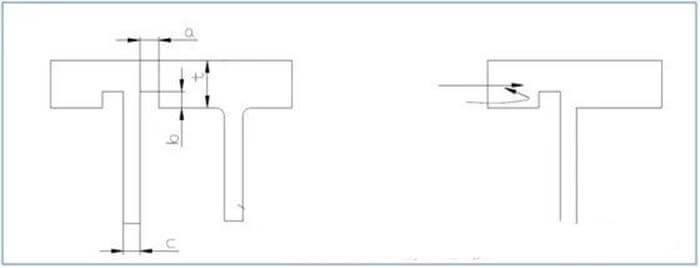
- The following parts should meet: b=1/4~1/3t; a=1/2c, Figure 2 One-sided recess should be opened on the side of the gate flow to avoid direct impact on the column.
- The injection moulding die design should consider the space for the robot to take out.
- The fastest speed of mold erection is 6 seconds i.e. fully automatic mold erection, one injection molding machine 200,000. (Using the mold pre-heated water hole, injection moulding die design when the water hole is connected, racking mold only leave in the water outlet. The mold erection speed in Taiwan is about 3 minutes.
- A cut-off gate in the mold and optical parts are used more often.
- Relationship between runner and quality: (especially when forming lenses)
- Calculation of mold strength should take into account: molding clamping force, template strength, mold kernel strength, etc.
- Inserts can be vacuum-attracted.
The 141 to 150 injection moulding die design experiences
- The pressure sensor, used to detect the pressure loss inside the mold, is sometimes designed at the end of the ejector pin (for small parts). Large parts can sometimes be placed directly inside the mold cavity.
- Japanese molding machines can set up to 10 levels of parameters (pressure, injection speed, and good quality molding machine parameters are generally not drifted after setting.
- The contact pressure between the filling head and the mold of the molding machine is about 6 tons, and below 45 tons is about 3 tons.
- Increasing the hardness of beryllium copper can be plated with hard chrome, generally pouring molding.
- Blasting materials: glass sand, alumina, walnut powder, iron sand.
- Glass shot size: #200, #150, #400.
- The relationship between forming material and forming volume between molds: NAK-80 for molds with a low output. g: glass fiber c: carbon fiber
- For most of the parts of the machine, it is good to use hot sprue, and there is a heating system in the mold. There are three kinds of hot sprue: full hot sprue, half hot sprue, half – half hot sprue.
- Heat insulation board is used in the molding machine, located in front and back of the mold, using glass fiberboard or bakelite, the former is 5 times the price of the latter, used for mold temperature high, optical parts, carbon fiber 20% or more.
- SLIDE backward because the block is too small, and then make a similar block to solve, or the wedge tight block front processing pointed some.
The 151 to 160 injection moulding die design experiences
- The cooling methods of the mold are water, frozen water (-5℃), oil, and electric heaters.
- The minimum can wire cut 0.14 hole, 1MM deep, use Φ0.03 wire to wire cut, thread the hole with LASER processing, chemical corrosion can be processed at least Φ0.4 hole.
- A flat thimble is easy to run burr and jam, so use it as little as possible. Generally, it is better to make 0.5 and above. 0.5 below its effective distance.
- The temperature sensor is divided into K (CA) TYPE CI TYPE.
- If the inlet does not move, t can be as low as 0.2mm, if the inlet moves, t is 0.5~0.7mm (0.6mm).
- If the upper part of the part is convex and the upper part of the die is concave, use a knife to carve it directly during processing.
The word on the part is concave and the word on the die insert is convex, which is finished by electrode discharge.
If you want the part with the word to be brighter, first discharge the word and polish it to the required brightness, and then discharge the whole surface, but when discharging, avoid emptying the processed part of the word on the electrode.
If the surface has appearance requirements, it should be nibbled first, and then process the word.
- The flow channel of the lens mold is generally round, with a fixed side and a movable side in each half.
- In the two-plate mold, when the length of the main flow channel > 60, can be used without filling mouth form, that is, the fixed side of the mold kernel made into the filling mouth, 101 plates from the positioning ring into a conical hole, molding, directly into the 201 filling mouth.
- When processing the roller, the fixed side mold kernel and movable side mold kernel first grind the bevel, its verticality can be guaranteed (within 5umm), and then lock the two mold kernels with screws, grinding plane (with the naked eye looks fit line is not easy to see), and then line cutting hole.
- When designing the gear, pay attention to the direction of parts placement, as shown in the diagram: external gear parts, mold kernel on the line cutting line to stay at the arrow shown is appropriate.
The 161 to 170 injection moulding die design experiences
- The chamfering angle of the line cutting into the sub can be R angle, but also can be a right angle, line cutting the inner hole chamfering angle must be R angle, in the matching mold can be R angle matching, but also the inner hole chamfering angle clear angle matching mold, depending on the actual situation.
PT1/4*15[%%C10], 1/4 means the threaded hole diameter is 13.5, and 1/8 means the threaded hole diameter is 9.6.
- The cold material hole can grip the scrap, and the machining is done with a turning tool.
- plastic parts or stamping parts whose surfaces often need to print words, but how to test the firmness of its adhesion, methods are A with commonly used organic solvents, gasoline, or alcohol scrubbing. B with a strong tape stuck to the above, and then quickly tear up.
- For more into the son, complex structure of the mold molding 10000 times, (about a week or so need to maintain once), simple parts to 50,000 times, (about 10 days or so maintenance once). For plastic mold, it is very important to maintain and oil the moving parts, because a large amount of gas will be formed in the long-term molding, attached to the mold, affecting the smooth action.
- Polishing of coarse appearance electrode is #800 sandpaper, polishing of medium appearance electrode is #1200 sandpaper, polishing of fine appearance electrode is #1500~#2000 sandpaper.
- Use spark oil or kerosene as polishing fluid when polishing, so that the powder will not stick to the workpiece and sandpaper, and clean it by removing sewage after polishing.
- When measuring the parts, at least 3 modules are tested to be accurate, and 5 modules are measured in Taiwan when testing the body, and each module is measured in about 3 days.
- For the inch method that cannot be detected on the drawing, it should be proposed to the customer and determined by the group.
- Plating: ABS+CU+Ni+Cr, where CU is 20UMM thick, Ni is 10 UMM thick and Cr is 5 UMM.
170.Steam family: gold plating 0.3UMM~0.4UMM (pure gold).
The 171 to 180 injection moulding die design experiences
- The best R is at the hook of the parts, and the customer review, so that the parts are not easy to break.
- As shown below, the coaxiality and diameter can be easily ensured by the grinding machine, but the two-inch method here is not easy to ensure.
- Grinding machine classification: GC internal and external cylindrical grinding, JG (GN) cylindrical grinding processing, GF, GS surface grinding machine, GP (profile) projection grinding machine.
- Heat treatment is generally reserved at 0.20mm at present (YORKEY has been reserved at 0.04mm at least, and 0.10mm in general), and sometimes an electric furnace is used instead of vacuum heat treatment, but its surface will decarburize and turn black.
- on the template, mold kernel requirements: c / / d0.005 (general optical), 0.002 (special optical), six-sided perpendicularity parallelism 0.002MM or less (optical mold), can take the middle escape meat 2mm deep to achieve, the following chart: 216. matte test processing limit: 0.3UMM, in the production of special optical, should try to use grinding machine processing to ensure its processing accuracy.
- Mirror cylinder mold die sitting standard: 350X350; 400X400.
- In the selection of the injection machine, in addition, to ensure that the injection machine can be set into, also calculate the total injection weight of the mold
- Optical is divided into three categories: window; general optical; special optical.
- The original instrument is divided into original instrument (1): for measuring the original instrument; original instrument: for measuring the mold kernel; secondary original instrument: for detecting the processing of the old kernel.
- Special optical lenses are shown in the figure below: a diamond cutter is used to process the engraved line on the die kernel, and the line looks blurred for two reasons: one is the insufficient filling of the molding, and the other is that the processing is not a sharp angle, but a small plane.
The 181 to 185 injection moulding die design experiences
- processing spherical SR0.1MM, into the tool 1UMM,2 UMM.
- The tolerance of the die kernel is 1/5 of the tolerance of the part, and the tolerance of the electrode is 1/2 of the tolerance of the die kernel.
- In the determination of small R, such as R0.14, and R0.002, use the electron microscope magnification 500 times to determine. When the magnification reaches 50,000 times, the cold chlorine is turned off and automatically detected.
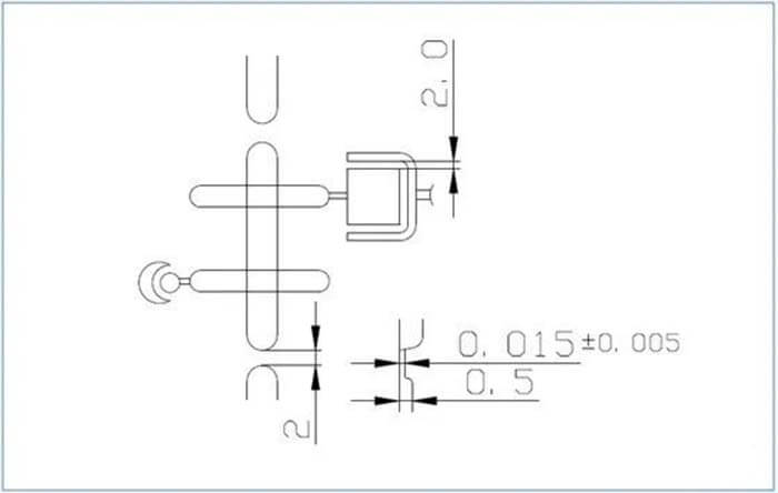
- The air escape is shown in the following figure inch method, the flow channel, and parts of the diagram shown in the first for the air escape.
- When a processing angle tolerance of 30′ or less, to design processing jig processing, must use surface grinding machine processing to meet the requirements.
Besides the 185 Injection Moulding Die Design Experiences article, you may also be interested in the below articles?
Summary Of 50 Injection Mold Structure Operation Dynamic Diagrams
Auto Parts Stamping Die Design Concept