This article talks about the Analysis and countermeasures of flow lines in injection molded products.
Analysis and countermeasures of flow lines in injection molded products
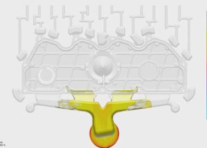
Classification of flow lines in injection molded products
1) Snake lines
When the melt enters the mold cavity from the gate, it produces a jet effect and appears on the surface of the product like a snake, so it is called snake flow lines.
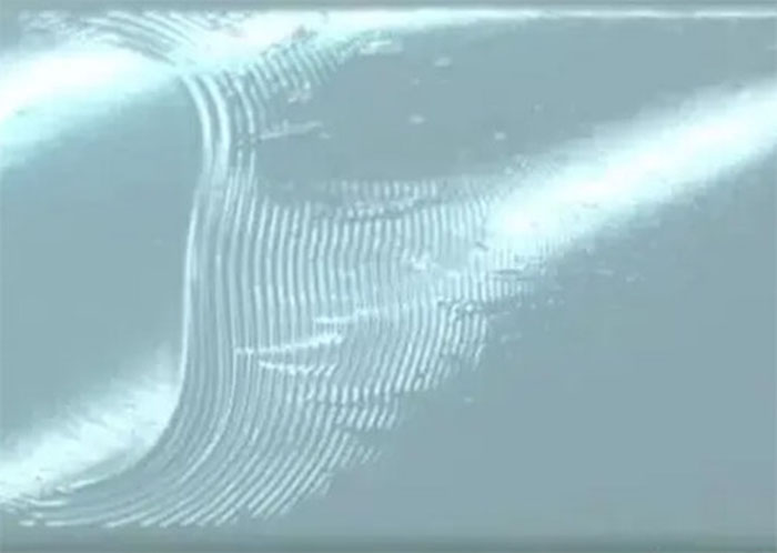
2) Wave lines
The melt flow in the mold cavity is not stable, sometimes fast and sometimes slow, and it appears on the surface of the product like waves, so it is called wandering.
3) Radiation lines
Generally, it only appears near the gate. When the melt enters the mold cavity, it sprays, which is radial on the surface of the product, so it is called a radial line.
4) Fluorescent lines
The shear stress generated by the melt flow causes the surface of the product to produce a luster that is very similar to the body of a firefly, so it is called a fluorescent line.
The solution to flow lines in injection molded products
1) Snake flow lines
When the gate depth is much smaller than the cavity entrance depth, and the mold filling rate is very high, when the melt flow becomes unstable jet flow, the front jet has solidified and the later flowing melt fills the mold cavity, and the product will be Snake flow lines appear on the surface.
Solution
① Change the process conditions.
The method of reducing the injection rate will gradually eliminate the jet effect and expand the flow of the melt flow. The expanded flow will make the product have a better surface quality; in addition, increasing the mold temperature and melt temperature will also reduce the jet effect and expand the melt flow.
② Change the gate size of the mold.
When the gate depth is slightly smaller than the cavity depth, the outlet expansion of the jet will fuse the melt behind and the leading edge of the jet that is not far out in front, so that the jet effect is not obvious. When the gate depth is equal to or close to the depth of the cavity, the mold filling rate is low and an expanding flow is formed.
③Change the angle of the mold gate.
Make the angle between the mold gate and the mold movable mold 4o ~ 5o, so that when the melt flows out from the gate, it will first be blocked by the cavity wall, which can prevent the appearance of snake flow.
④ Change the gate position of the mold.
Set the mold gate at the closest position to the mold cavity wall (perpendicular to the gate direction). When the melt flows out of the gate, it will first be blocked by the cavity wall, and it can also prevent the jet from appearing and make it a Expand the flow to avoid the appearance of snake flow.
2) Wave lines
During the melt filling process, the new melt flow is continuously laminated from the inside, pushing the forward wave stagnation flow to move, and at the same time, the forward wave edge is constantly stretched.
Due to the flow resistance, the later melt-pressure rises and the front The newly formed corrugations are flattened and advanced, causing the stagnant flow to accumulate, thereby forming wavy patterns on the surface of the product.
Especially when the injection rate is fast, the injection pressure is low or the mold structure is unreasonable, the melt flow will stop and the PP will crystallize quickly and slowly, which will cause the product surface crystallinity to be inconsistent and form the product surface wave lines.
Solution
① Change the process conditions.
The use of high-pressure and low-speed injection can maintain the stability of the melt flow and prevent the appearance of wave patterns.
②Increase the mold temperature.
As the mold temperature increases, the melt fluidity increases. For crystalline polymers, a higher temperature is beneficial to the uniformity of crystallization, thereby reducing the appearance of wave patterns.
③Change the cavity structure.
The structure of the mold can also cause waves to appear on the surface of the product. If the edges and corners of the mold core are more prominent, the melt flow resistance is greater, which will cause the melt flow to be unstable and form wave patterns.
Therefore, the edges and corners of the mold core are changed to buffer the transition, keep the melt flow stable, and prevent the appearance of wave patterns.
④ Change the thickness of the product.
The uneven thickness of the product will cause the melt flow resistance to be large or small, resulting in unstable melt flow. Therefore, the product thickness should be designed as a uniform thickness as much as possible to prevent the appearance of wave patterns.
3) Radiation lines
If the injection rate is too large, when the melt is ejected, the melt is elastic. When the melt flows from the barrel to the mold cavity through the mold gate, the melt recovers too quickly, causing the melt to rupture and produce radial lines.
Solution
① Change the process conditions.
Using high-pressure and low-speed injection can increase the flow time of the elastic melt at the same flow length and increase the degree of elastic failure, thereby reducing the appearance of radial lines.
②Change the shape of the mold gate.
Enlarging the gate or changing the gate to a fan shape can restore the elasticity of the melt before the melt enters the cavity to avoid melt fracture.
③Extend the length of the main runner of the mold.
Before the melt enters the cavity, its elasticity is invalidated, which can also avoid melt fracture.
④ Replace the equipment with an extended nozzle.
Lengthening the flow path of the melt before entering the mold cavity increases the degree of elastic failure of the melt, and can also avoid the occurrence of radial lines due to melting fracture.
4) Fluorescent lines
When the melt flows in the mold cavity, one end of the molecular chain close to the solidified layer is fixed on the solidified layer, and the other end is stretched along the flow direction by the adjacent molecular chain.
Since the melt flow resistance close to the cavity wall is the largest and the flow rate is the smallest, the flow resistance at the center of the cavity is the smallest, and the flow rate is the largest so that a velocity gradient is formed in the flow direction, so the injection rate is small and the injection pressure is large.
Or when the product is thinner, the melt shearing force near the cavity wall is the strongest and the orientation is the largest. The polymer is stretched during the flow and exhibits internal stress, resulting in fluorescent lines on the surface of the product.
Solution
① Change the process conditions.
With medium-pressure and medium-speed injection, as the injection rate increases, the cooling time of the melt in the same flow branch length decreases, the solidification of the melt per unit volume is relatively slow, the internal stress of the product is weakened, and the appearance of fluorescent lines on the surface of the product is reduced.
② Increase the mold temperature.
Relative mold temperature can accelerate the relaxation of macromolecules, reduce molecular orientation and internal stress, thereby reducing the appearance of fluorescent lines on the surface of the product.
③Change the cavity structure and increase the thickness of the product.
The thickness of the product is larger, the melt cooling is slower, the stress relaxation time is relatively prolonged, and the orientation stress will be reduced, thereby reducing the fluorescent stripes.
④ Heat treatment (baking in oven or boiling in hot water).
Heat treatment intensifies the movement of macromolecules, shortens the relaxation time, strengthens the de-orientation effect, and reduces the fluorescence lines.
You may also be interested in the below articles:
Summary Of 50 Injection Mold Structure Operation Dynamic Diagrams