Plastic injection mold structures can be divided into static and dynamic molds. Generally speaking, the injection mold structure consists of seven parts.
Pouring system injection mold structure
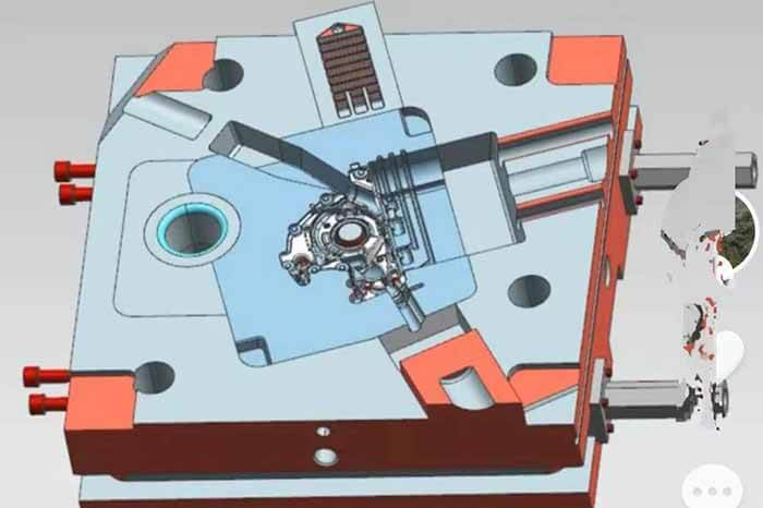
Molding parts, i.e. cavities
Mold venting injection mold structure
Push-out injection mold structure
Side core injection mold structure
Mold closing guide injection mold structure
Heating and cooling system injection mold structure
An injection molding is a tool for producing plastic products; it is also a tool for giving plastic products a complete structure and precise dimensions.
Injection molding is a processing method used for the mass production of certain complex-shaped parts. Specifically, the heat-melted plastic is injected into the mold cavity at high pressure by an injection molding machine, and after cooling and curing, the molded product is obtained.
The injection mold structure may vary depending on the variety and properties of the plastic, the shape and structure of the plastic product, and the type of injection machine, but the basic injection mold structure is the same.
The mold is mainly composed of a pouring system, temperature regulating system, molding parts, and structural parts.
Among them, the pouring system and molding parts are the parts in direct contact with plastic and change with plastic and products, which are the most complicated and changeable parts of the mold and require the highest processing finish and precision.
The injection mold consists of two parts: the moving mold and the fixed mold, which are mounted on the moving template of the injection molding machine, and the fixed mold on the fixed template of the injection molding machine.
During injection molding, the moving mold and the fixed mold are closed to form the pouring system and cavity, and during mold opening, the moving mold and the fixed mold are separated in order to remove the plastic products. In order to reduce the heavy workload of mold design and manufacturing, most of the injection molds adopt standard mold frames.
Pouring system of the injection mold structure
The pouring system is the part of the flow channel before the plastic enters the cavity from the injection nozzle, including the main flow channel, cold cavity, manifold, and gate.
The pouring system, also called the runner system, is a group of feed channels that lead the plastic melt from the injector nozzle to the cavity, usually consisting of the main flow channel, manifold, gate, and cold material cavity.
It is directly related to the molding quality and production efficiency of plastic products.
Mainstream channel of the injection mold structure
It is a section of the mold that connects the injection nozzle of the injection molding machine to the manifold or cavity. The top of the main flow channel is concave so that it can be connected with the nozzle.
The main flow channel inlet diameter should be slightly larger than the nozzle diameter (0.8mm) to avoid overflow and prevent the two from blockage due to inappropriate articulation.
Inlet diameter according to the size of the product, generally 4-8mm. main flow channel diameter should be expanded inward at an angle of 3 ° to 5 ° so that the runner is superfluous of the mold.
Cold material cavity of the injection mold structure
It is a cavity located at the end of the main flow channel to trap the cold material generated between the two injections at the end of the nozzle, so as to prevent the blockage of the manifold or gate. If the cold material once mixed into the cavity, the products made will be easy to produce internal stress.
The cold material cavity is about 8-10 mm in diameter and 6 mm in-depth, and the bottom of the cavity is often covered by a release bar for easy release.
The top of the mold release rod should be designed into a zigzag hook shape or set up a sunken groove so that the mold can be smoothly pulled out of the main flow channel superfluous.
Diversion channel of the injection mold structure
It is the channel connecting the main flow channel and each cavity in the multi-slot mold. In order to make the melt fill the cavities with equal speed, the arrangement of the manifold on the mold should be symmetrical and equidistant distribution.
The shape and size of the cross-section of the manifold have an effect on the flow of the melt, the release of the product, and the ease of mold making.
If the flow of the same amount of material, the flow channel with circular cross-section has the least resistance. However, the cylindrical flow channel has a small surface, which is not conducive to the cooling of the manifold, and the manifold must be opened on both halves of the mold, which is labor-intensive and not easy to align.
Therefore, manifolds with trapezoidal or semi-circular cross-sections are often used and are opened on one half of the mold with a release lever. The runner surface must be polished to reduce flow resistance and provide a faster filling speed.
The size of the runner depends on the type of plastic, the size, and the thickness of the product. For most thermoplastics, the cross-sectional width of the runner should not exceed 8 mm, from 10-12 mm for very large ones to 2-3 mm for very small ones, and the cross-sectional area should be reduced as much as possible to increase the runner bulk and prolong the cooling time.
Gate of the injection mold structure
It is the channel to connect the main flow channel (or shunt channel) and the cavity. The cross-sectional area of the channel can be equal to that of the main flow channel (or manifold), but it is usually reduced. Therefore, it is the smallest part of the entire runner system.
The shape and size of the gate have a great influence on the quality of the product.
The function of the gate is to:
- control the speed of material flow
- Prevent backflow during injection because of early solidification of the melt stored in this part
- The melt through the strong shear and raise the temperature, thereby reducing the apparent viscosity to improve mobility
- Easy to separate the product from the runner system
The design of gate shape, size, and location depend on the nature of the plastic, the size, and the structure of the product. Generally, the cross-sectional shape of the gate is rectangular or round, the cross-sectional area should be small and the length should be short, not only based on the above-mentioned role, but also because it is easier to make a small gate bigger, while it is difficult to make a big gate smaller.
The location of the gate should generally be chosen in the thickest part of the product without affecting the appearance. The design of the gate size should take into account the nature of the plastic melt.
The cavity is the space in the mold where the plastic product is molded. The components used to form the cavity are collectively referred to as molding parts. Each molding part often has a special name.
The molding parts that form the shape of the product are called concave mold (also known as the negative mold), and those that form the internal shape of the product (such as holes, slots, etc.) are called cores or convex mold (also known as the positive mold).
When designing molding parts, the first thing is to determine the overall structure of the cavity according to the properties of the plastic, the geometry of the product, size tolerance, and use requirements.
The second is to choose the location of the parting surface, gates, and venting holes as well as the demolding method according to the determined structure.
Finally, the design of each part and the combination of each part are determined according to the size of the control product.
The plastic melt enters the cavity with high pressure, so the molding parts should be reasonably selected and the strength and stiffness should be checked.
In order to ensure the surface of the plastic products and easy to take off the mold, the surface in contact with the plastic, its roughness Ra>0.32um, and to resist corrosion.
Molding parts are generally heat-treated to improve the hardness and the choice of corrosion-resistant steel manufacturing.
The temperature control system of the injection mold structure
In order to meet the requirements of the injection process on the temperature of the mold, there is a need for a temperature regulation system to regulate the temperature of the mold. For thermoplastic injection molds, the cooling system is mainly designed to make the mold cool.
The common way to cool the mold is to open a cooling water channel in the mold, using the circulating cooling water to take away the heat of the mold; the heating of the mold can be used in addition to the cooling water channel hot water or steam, but also in the mold and around the installation of electric heating elements.
The molding parts of the injection mold structure
Molding parts are the various parts that constitute the shape of the product, including moving mold, fixed mold, cavity, core, molding rod, exhaust port, etc. The molding parts are composed of a core and concave mold.
The core forms the inner surface of the product and the concave mold forms the outer surface of the product. After the mold is closed, the core and the cavity form the cavity of the mold. According to the process and manufacturing requirements, sometimes the core and concave die are combined by a number of pieces, sometimes made into a whole, only in the easily damaged, difficult to process parts using inserts.
Exhaust port of the injection mold structure
The exhaust port of the injection mold structure is a kind of slot-shaped air outlet opened in the mold to discharge the original and the gas brought in by the melt.
When the molten material is injected into the cavity, the original air in the cavity and the gas brought in by the melt must be discharged at the end of the material flow to the mold through the exhaust port, otherwise, it will make the product with air holes, poor connection, mold filling, and even the accumulated air due to the high temperature generated by the compression and the product will be burned.
In general, the exhaust hole can be located either at the end of the melt flow in the cavity or on the parting surface of the mold. The latter is in the concave mold side to open a shallow groove 0.03-0.2mm deep and 1.5-6mm wide.
In the injection, the venting hole will not have a lot of melt seepage, because the melt will be cooled and cured at the place to block the channel. The venting position should not be facing the operator to prevent the melt from accidentally ejecting and injuring people.
In addition, you can also use the ejector rod and the ejector hole clearance, the top block, and stripper plate, and the core of the clearance to exhaust.
The injection mold structure of the parts
It refers to the various parts that constitute the structure of the mold, including guide, mold release, core extraction, and various parts of the parting. Such as injection mold clamp, front and rear clamping plate, front and rear clamping plate, bearing plate, bearing bushing, guiding bushing, demoulding plate, demoulding rod and return rod, etc.
Guiding parts of the injection mold structure
In order to ensure the accurate centering of the moving mold and the fixed mold when closing the mold, guiding parts must be set in the mold. In the injection mold, four sets of guide pillars and guide bushings are usually used to form the guiding parts, and sometimes it is also necessary to set up the inner and outer cone surfaces on the moving mold and the fixed mold respectively to assist in positioning.
Pushing out mechanism of the injection mold structure
In the process of mold opening, there is a need to push out the mechanism to push out or pull out the plastic products and their condensed materials in the flow channel. Push out the fixed plate and push plate for clamping the push rod. In general, there is also a reset lever fixed in the push rod, the reset lever in the dynamic, fixed mold to reset the push plate when the mold is closed.
Side core extraction mechanism of the injection mold structure
Some plastic products with side concave or side hole, before being pushed out, must first carry out the lateral parting, pull out the lateral core before the smooth release of the mold, then need to set up the side core mechanism in the mold.
An injection device is a device that makes resin material melt by heat and then injects it into the mold. The resin is squeezed into the barrel from the material head, and the melt is conveyed to the front end of the barrel by the rotation of the screw.
In this process, the resin material inside the barrel is heated under the action of the heater, and the resin becomes molten under the action of the shear stress of the screw, which will be equivalent to the molded product and the main flow channel, and the molten resin of the diversion channel is retained in the front end of the barrel (called metering), and the constant forward movement of the screw shoots the material into the mold cavity.
When the molten resin flows in the mold, the movement speed of the screw must be controlled (injection speed) and controlled with pressure (holding pressure) after the resin fills the mold cavity.
When the screw position and injection pressure reach a certain value we can switch from speed control to pressure control.
Besides the What is the Injection Mold Structure article, you may also be interested in the below articles.
Summary Of 50 Injection Mold Structure Operation Dynamic Diagrams
Auto Parts Stamping Die Design Concept