Design Of Stamping Process Of Automobile Reinforced Cover
In the design process of automobile cover molds with large external dimensions, small material thickness, and complex shapes, the stamping process must not only ensure the production of qualified parts but also meet the low-cost design concept.
Taking a certain type of automobile reinforced cover plate as an example, a numerical simulation analysis software was used to develop the drawing forming ➝ trimming punching ➝ bending shaping ➝ oblique punching separation process plan. After die manufacturing and debugging, the final stamping obtained qualified stamping parts.
Reinforced cover plates for automobiles are internal supports, and their appearance requirements are not stringent. However, there should be no defects such as insufficient forming and micro-cracks on the parts, because this will cause adverse effects or hidden safety hazards to parts or the entire vehicle.
Therefore, when formulating process specifications, the safety and reliability of the use of parts must be considered, and of course, the cost-effectiveness of mold equipment must also be considered.
1. Feature analysis
Figure 1 shows a certain type of automobile reinforced cover plate, which is an interior part. Its material is cold-rolled carbon steel sheet SPCC (C≤0.15, Mn≤0.6, P≤0.1, S≤0.05, and the rest of Fe), equivalent to Q215A, Material thickness t=0.8mm, basic size 307.5×172×73.9mm.
The part is closed in three directions, and the opening in the negative direction is x so that the mold is designed as one mold and two parts, and then the four-way closure can be achieved, which is conducive to the stretching and forming of the part and avoids the deviation of the forming.
Based on the k-line, the upper part of the sidewall is generally concave, the angle between the sidewall and the bottom is approximately 95°, and two additional concave types are added, as shown by the two circles on the right side of Figure 1;
The convex part of the sidewall under the k-line is basically straight, and there are also two irregular recesses, as shown in the circle under the k-line in Figure 1; and the part shown at the bottom circle is at a different angle, which will cause complexity to the forming.
Therefore, it is at the same height as the bottom surface of the part. In addition, the top of the article also has concave and convex shapes, and at the same time, the article also has openings with different shapes and different orientations at various positions.
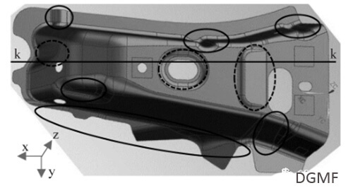
Figure 1 Product model
2. Workpiece stamping process plan
The stamping process of automobile cover parts mainly includes blanking, stretching, trimming, flanging, shaping, punching, and separation. When formulating the stamping process plan, it is necessary to consider the difficulty of manufacturing the mold and the manufacturing cost; at the same time, we must also pay attention to the number and sequence of processes. The former involves the total cost of the mold equipment, and the latter affects the stamping quality of the parts.
After analyzing the shape and structure of the part, with the assistance of the finite element analysis software for stamping forming, the stamping process plan is determined.
The first process (OP10) is a stretch forming process, as shown in Figure 2. It can be seen from the three-dimensional drawing that when the forming process is designed, all holes and openings on the digital mold must be repaired along with its current position, and all bottom surfaces should also be placed at the same height to facilitate the pressing;
Shown as a draw bead, its main function is to increase the feed resistance and balance the feed rate of the perimeter of the part, and effectively prevent defects such as insufficient forming and wrinkling. After calculation, the forming force in this process is about 95t, the blank holder force is about 31t, and the working stroke is about 81mm. Fig. 3 shows the part of the drawing and forming process for this product.
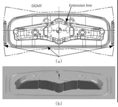
Figure 2 Stretch forming process
a is 2D graph; b is 3D graph
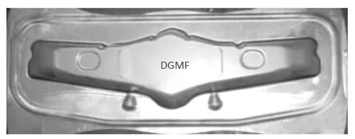
Figure 3 Stretch forming process parts
As shown in TRIM, according to the contour of the trimming line, the excess part is removed from the stretched part, mainly referring to the supplementary part of the forming process;
② The second is punching, as shown in PI in FIG. 4, that is, punching the hole in the direction of the trimming, it is also a hole that is closed for forming needs;
③ The third is to cut waste, as shown in WK in FIG. 4, mainly because the size of the automobile parts is large, the rigidity of the trimming waste is hollow when it is hollow, and it is not easy to remove.
Therefore, waste is often set The knife cuts the irregular ring-shaped waste into multiple sections according to the specified size, and then falls to the waste chute under the action of gravity and enters the waste collection basket. Therefore, the position of the waste knife must consider the maximum size, gravity point, and contour characteristics of each section of waste. After calculation, the required punching force of this process is about 60t, and the pressing force is about 3.5t.
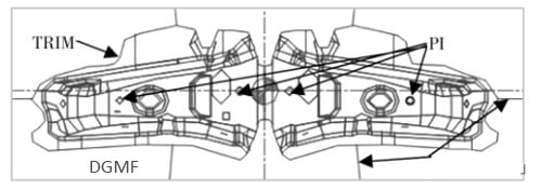
Figure 4 Trimming/punching composite process
The third process is bending/shaping, as shown in Figure 5. The main reasons for the setting of this process are as follows:
① First, because the local shape of the part is too complicated, the first drawing process cannot meet the shape requirements of the part, because it may cause the shape of the drawing convex and concave mold to be complicated, making it difficult to manufacture and repair the die;
② The second is that it may cause wrinkling and crack of the tensile parts;
③ The third is that there is a negative forming angle at a local position.
Therefore, when the various forming factors are fully considered, and the drawing process cannot meet the final shape requirements of the part, additional forming processes such as shaping, bending, and flanging are required. After calculation, the punching pressure required in this process is about 18t, and the pressing force is about 3.5t.
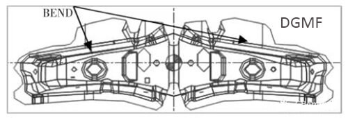
Figure 5 Bending/shaping composite process
The fourth process is a separation/side punching composite process, as shown in FIG. 6.
This procedure includes two working actions:
① One is lateral punching, as shown by C-PI in Fig. 6, relying on an inclined wedge to convert vertical punching pressure into inclined/angle punching pressure to reach the sidewall of punched parts or The purpose of the hole with an oblique angle;
② The second is the separation action, as shown in SEP in FIG. 6, the workpiece is divided into two by the cutting knife, so as to realize one mold and two pieces. After calculation, the punching pressure required in this process is about 22t, and the pressing force is about 1.5t.
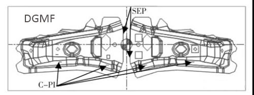
Figure 6 Separation/side punching composite process
3. Conclusion
Combined with the shape characteristics of the automobile reinforced cover plate, the sheet forming simulation software is used to simulate the stretch forming to obtain the relevant parameters of the first process, and then design the subsequent processes such as trimming, punching, shaping, separation, etc.
The main conclusions are as follows :
①The drawing process is the first process in the design of automobile molds, and the orientation and positioning of the parts are important, which affects the difficulty of the subsequent process;
②The position and layout of the scrap knife in the trimming/punching process Seriously affects whether the material is smoothly removed, and at the same time, the choice of punching combination can also affect the layout of the punch and the reliability of the pressing;
③ Based on the principle of process economics, shaping and flanging are only considered when the stretch forming cannot meet the shape requirements of the part Wait for the secondary forming process.
You may also be interested in the below articles:
Summary Of 50 Injection Mold Structure Operation Dynamic Diagrams