What is geometric tolerance in injection molding?
Geometric tolerances, it is both theoretical and practical expertise.
In production, if we misunderstand the geometric tolerances marked on the drawings, it will deviate the processing analysis, processing results, and requirements, and even bring serious consequences. Today, let us take a systematic look at the 14 geometric tolerances.
1. Straightness
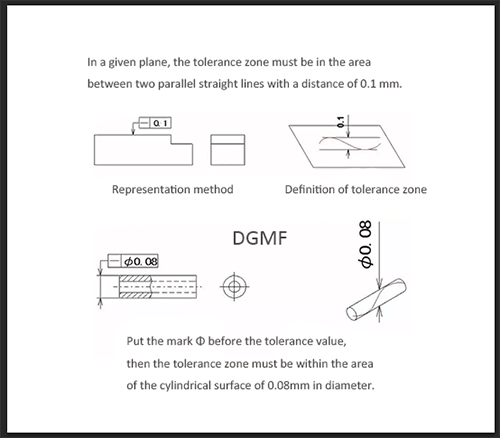
Straightness, which is commonly referred to as the degree of straightness, means that the actual shape of the linear elements on the part maintains an ideal straight line. The straightness tolerance is the maximum allowable variation of the actual line to the ideal straight line.
Example A: In a given plane, the tolerance zone must be in the area between two parallel straight lines with a distance of 0.1 mm.
Example B: If the mark Φ is added before the tolerance value, the tolerance zone must be within the area of a cylindrical surface with a diameter of 0.08 mm.
2. Flatness
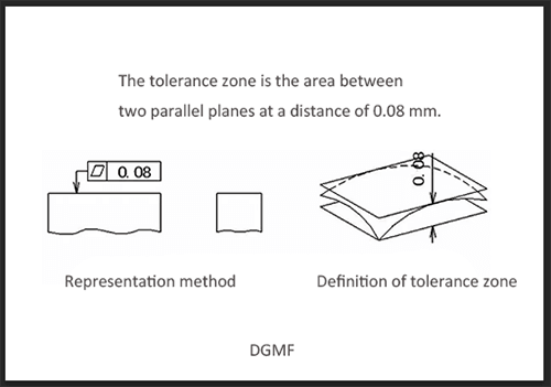
Flatness, which is commonly referred to as the degree of flatness, represents the actual shape of the planar elements of the part and maintains the ideal plane. Flatness tolerance is the maximum allowable variation of the actual surface from the ideal plane.
Example: The tolerance zone is the area between two parallel planes with a distance of 0.08 mm.
3. Roundness
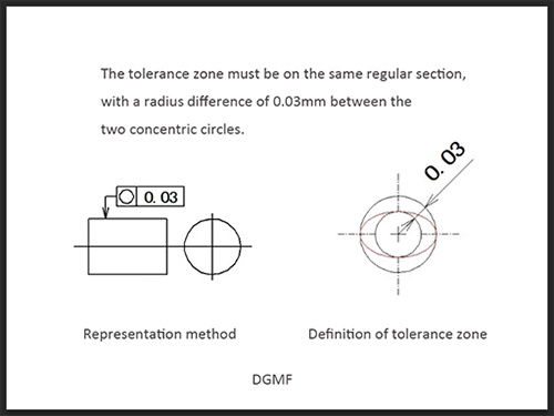
Roundness, commonly known as the degree of roundness, means that the actual shape of a round element on a part remains equidistant from its center. The roundness tolerance is the maximum allowable variation of the actual circle to the ideal circle in the same section.
Example: The tolerance zone must be on the same regular section and the radius difference is the area between two concentric circles with a tolerance value of 0.03mm.
4. Cylindricity
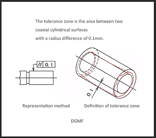
Cylindricity means that the points on the outline of the cylindrical surface of the part are kept equidistant from their axes. Cylindricity tolerance is the maximum variation allowed by the actual cylinder facing the ideal cylinder.
Example: The tolerance zone is the area between two coaxial cylindrical surfaces with a radius difference of 0.1mm.
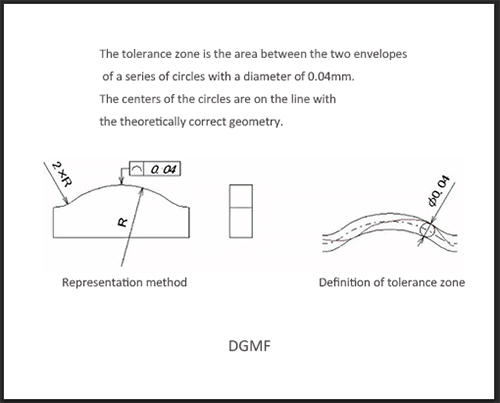
5. Line profile
The line profile is the condition of a curve of any shape on a given plane of a part, maintaining its ideal shape. The line profile tolerance refers to the allowable variation of the actual outline of a non-circular curve.
Example: The tolerance zone is the area between the two envelopes of a series of circles with a tolerance of 0.04 mm in diameter. The centers of the circles are on the line with the theoretically correct geometry.
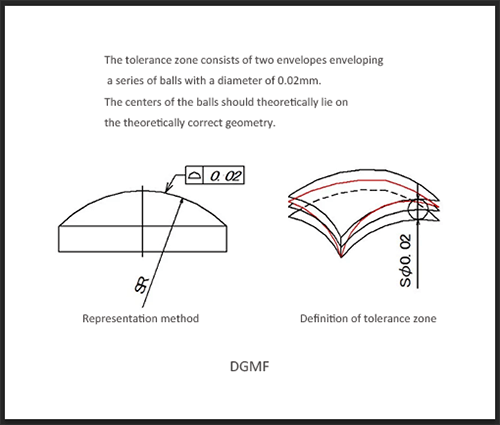
6. Surface profile
The surface profile is a condition that represents a curved surface of any shape on a part and maintains its ideal shape. The surface profile tolerance refers to the actual contour of a non-circular curved surface and the allowable variation of the ideal contour surface.
Example: The tolerance zone consists of two envelopes enveloping a series of balls with a diameter of 0.02 mm. The centers of the balls should theoretically lie on the theoretically correct geometry.
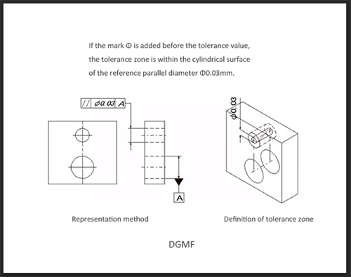
7. Parallelism
Parallelism, commonly known as the degree of parallelism, means that the actual elements on the part are kept at equal distances from the reference. Parallelism tolerance is the maximum allowable variation between the actual direction of the measuring element and the ideal direction parallel to the reference.
Example: If the mark Φ is added before the tolerance value, the tolerance zone is within the cylindrical surface of the reference parallel diameter Φ0.03mm.
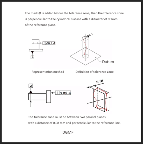
8. Verticality
The perpendicularity, that is, the degree of orthogonality between the two elements, which means that the measuring element on the part maintains a correct angle of 90° relative to the reference element. The perpendicularity tolerance is the actual direction of the measuring element and the maximum allowable variation between the ideal directions perpendicular to the reference phase.
Example A: The mark Φ is added before the tolerance zone, then the tolerance zone is perpendicular to the cylindrical surface with a diameter of 0.1 mm of the reference plane.
Example B: The tolerance zone must be between two parallel planes with a distance of 0.08 mm and perpendicular to the reference line.
9. Tilt
The inclination is the correct condition to indicate that the relative directions of the two elements on the part are kept at any given angle. The inclination tolerance is the actual direction of the measured element and the maximum allowable variation between the ideal directions at any given angle to the reference.
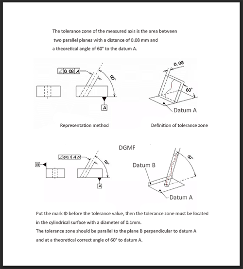
Example A: The tolerance zone of the measured axis is the area between two parallel planes with a distance of 0.08 mm and a theoretical angle of 60° to the reference plane A.
Example B: If the mark Φ is added before the tolerance value, the tolerance zone must be located on a cylindrical surface with a diameter of 0.1 mm. The tolerance zone should be parallel to plane B perpendicular to datum A and at a theoretical correct angle of 60° to datum A.
10. Position
The degree of position refers to the accuracy of the point, line, surface and other elements on the part relative to its ideal position. Position tolerance is the maximum allowable variation of the actual position of the measured element relative to the ideal position.
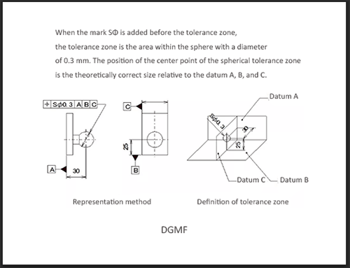
Example: When the mark SΦ is added before the tolerance zone, the tolerance zone is the area within the sphere with a diameter of 0.3 mm. The position of the center point of the spherical tolerance zone is the theoretically correct size relative to the benchmarks A, B, and C.
11. Coaxial (concentric) degree
Coaxiality, commonly referred to as the degree of co-axiality, means that the measured axis on the part remains on the same straight line relative to the reference axis. The coaxiality tolerance is the allowable variation of the measured actual axis relative to the reference axis.
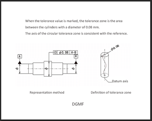
Example: When the tolerance value is marked, the tolerance zone is the area between the cylinders with a diameter of 0.08 mm. The axis of the circular tolerance zone is consistent with the reference.
12. Symmetry
Symmetry refers to the state in which two symmetric center elements on a part remain in the same center plane. Symmetry tolerance is the allowable variation of the actual symmetry center plane (or centerline, axis) of the ideal symmetry plane.
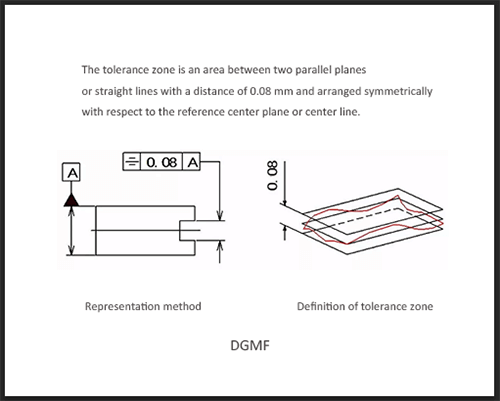
Example: The tolerance zone is an area between two parallel planes or straight lines with a distance of 0.08 mm and arranged symmetrically with respect to the reference center plane or centerline.
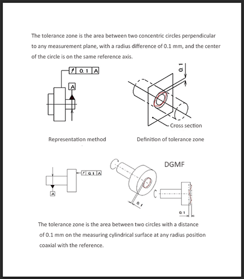
13. Circle beat
Circle beat refers to the situation where the rotating surface on the part is within a defined measurement plane and remains in a fixed position relative to the reference axis. The circular beat tolerance is the maximum allowable variation within the limited measurement range when the measured actual element rotates a full revolution around the reference axis without axial movement.
Example A: The tolerance zone is the area between two concentric circles perpendicular to any measurement plane, with a radius difference of 0.1 mm, and the center of the circle is on the same reference axis.
Example B: The tolerance zone is the area between two circles with a distance of 0.1 mm on the measuring cylindrical surface at any radius position coaxial with the reference.
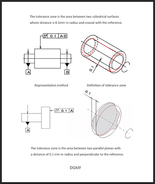
14. Full beat
Full run-out refers to the amount of run-out along the entire measured surface when the part rotates continuously around the reference axis. The full beat tolerance is the maximum allowable beat when the actual element under test is continuously rotated around the reference axis, and the indicator moves relatively along its ideal contour.
Example A: The tolerance zone is the area between two cylindrical surfaces with a distance of 0.1 mm in radius and coaxial with the reference.
Example B: The tolerance zone is the area between two parallel planes with a distance of 0.1 mm in radius and perpendicular to the reference.
You may also be interested in the below articles:
Summary Of 50 Injection Mold Structure Operation Dynamic Diagrams