Various Inclined Top Ejection Structures Of Injection Mold
This article analyzes various slanting top ejection mechanisms of injection molds, explains their respective advantages and disadvantages, and has a certain guiding role for technical personnel engaged in injection mold design and related work.
1. Selection of the parting line position of the connecting part of the inclined top and the injection part
The simple buckle is shown in Figure 1 ~ Figure 3 three different types of the inclined top part of the structure for a brief description.
From the comparison of the advantages and disadvantages, it can be seen that the injection flash (flash) in Figure 2 and Figure 3 will have a small effect on the assembly effect of the plastic parts, and Figure 2 is easier to demold than the structure shown in Figure 3.
Therefore, when the slider space is sufficient, the parting structure shown in FIG. 2 is preferred.
Figure 1 Type of inclined roof
Advantages: simple structure, easy to demold, and not easy to deform.
Disadvantages: The burr surface is above the sloping top of the buckle, and the assembly process is easily taken to the buckle assembly surface to affect the assembly.
Figure 2 Inclined roof type
Advantages: easy to demold, and the burr surface does not affect the assembly.
Disadvantages: The slanting surface of the buckle is easy to produce a slight step.
Figure 3 Inclined roof type
Advantages: rough surface does not affect the assembly.
Disadvantages: Relatively difficult to demold and easily deformed.
Connection method between the inclined roof and inclined roof seat
Take 5 different inclined roof seat structures shown in Figures 4 to 8 as a comparison and explanation.
(1) The structure shown in Figure 4 wears a sliding shaft in the middle of the inclined top and then installs a sliding wheel at each end of the sliding shaft.
Advantages: Both the sliding shaft and the sliding wheel can roll. When one of the slides is stuck, the other can still slide, which can more effectively prevent the inclined top from moving sideways.
Disadvantages: the sliding shaft and the sliding wheel need to be manufactured and assembled, the manufacturing cost is relatively higher, and the assembly is more troublesome.
(2) The structure is shown in Fig. 5 is based on Fig. 4, the sliding wheel is omitted, and the sliding groove is directly machined to the inclined top seat.
Advantages: omit the processing of sliding wheels, and simplify the assembly process.
Disadvantages: When the sliding shaft and the inclined top are stuck, the friction between the sliding shaft and the inclined top seat will be increased, and the sliding shaft has always been subject to a fixed force in the ejecting direction, which is easy to bend and jam.
(3) The structure shown in Figure 6 directly grinds the lateral sliding groove on the inclined top. If the size of the inclined top is large, the guide grooves are generally ground on both sides; if the size of the inclined top is small, only the guide grooves are ground on one side.
Advantages: low grinding cost and high precision, easy fitter mold matching.
Disadvantages: The lateral sliding surface is relatively large, and it is relatively easy to be stuck due to the lateral force. The oil tank needs to be processed, and the lower mold should be maintained regularly.
(4) Compared with the structure shown in Fig. 6, the structure shown in Fig. 7 changes the grinding right-angle guide groove to an arc-shaped guide groove. The anti-seizure has been slightly improved, but it requires wire cutting to process the slanted top and the curved wire groove of the slanted top seat, and the cost is high.
(5) Compared with the previous ones, the structure shown in Figure 8 mainly eliminates the sloping top hanging platform, and lengthens the sloping top seat and shortens the sloping top. Basically, this structure can be adopted in FIGS. 4 to 7.
Advantage one: the hanging platform of the oblique top seat is eliminated, and it is fixed to the thimble push plate through the screw hole on the back, which simplifies the demoulding process.
As long as the screws on the back of the inclined top seat are loosened first, the inclined top can be removed first.
Advantage two: shorten the length of the inclined top, effectively reduce the risk of bending deformation of the inclined top, and can reduce the wire cutting process.
Disadvantages: the connection between the inclined top and the inclined top seat needs to be strengthened and guided to control, otherwise it is easy to be deformed and stuck due to the lateral moving force of the inclined top.
Through the above comparison, if the production capacity requirements of plastic parts are relatively high, it is more recommended to use the sliding shaft plus sliding wheel structure shown in Figure 4.
Although the manufacturing and assembling process of this structure is a little more troublesome, the structure is relatively stable, and it is relatively difficult to get stuck. If the inclined top structure is relatively large, the solution shown in FIG. 8 may also be considered.
The inclined top seat is lengthened and the inclined top hanging platform is eliminated, and screw-locked to the thimble push plate. Of course, if the production capacity of plastic parts is not large, you can choose a more suitable structure according to the machining equipment of each mold factory.
Figure 4 Structure of inclined roof seat
Figure 5 Structure of inclined roof seat
Figure 6 Structure of inclined roof seat
- Movable template
- Inclined top guide block
- Inclined top
- Inclined top seat
- Top pole fixing plate
- Inclined top seat hanger
- Top pole push plate
- Inclined top sliding wheel
9. 10. Inclined top Sliding shaft
- Sliding shaft guide groove on inclined top seat
- Double-sided inclined top guide groove
- The single-side inclined top guide groove
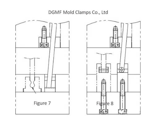
Figure 7 Structure of inclined roof seat
Figure 8 Structure of inclined roof seat
Various forms of the inclined roof structure
Take 5 different sloping roof structures as shown in Figure 9 to Figure 13 for comparison. Figure 9 ~ Figure 12 is a common inclined roof structure.
(1) The inclined roof structure shown in Figure 9 is reset by using the collision surface on the inclined roof, and spring is installed at the bottom of the inclined roof, and the mold is automatically ejected to release the buckle.
Advantages: simple structure and convenient processing.
Disadvantages: It is not safe to eject by the spring, it is easy to be stuck, and it is easy to deform the plastic parts. It is only suitable for the simplified mold for making a small number of samples.
(2) On the basis of Figure 9, if the top surface of the inclined top does not have a penetration surface, a reset pin can be added to the parting surface as shown in Figure 10.
The back of the slanted top is ejected by a jack, of course, the back can also be in the form of a spring pop. The advantages of FIG. 10 are the same as those of FIG. 9 and will not be repeated here.
(3) In the structure shown in Fig. 11, a ring-shaped concave groove is milled on the top of the top rod, and the bottom top is cut to match the structure.
Advantages: simple structure, convenient processing, and easy disassembly.
Disadvantages: The structural disadvantages shown in Figure 6 are that the lateral sliding surface is relatively large, and it is easy to be stuck due to the lateral force. It is not recommended for molds with large output.
(4) In the structure shown in Figure 12, when the top surface of the plastic part corresponding to the side core buckle is an acute-angled slope, in order to prevent the lateral movement of the inclined top from interfering with the plastic part, an equal angle can also be made on the inclined top seat Diagonal groove. The slanted top is pushed out while moving sideways at the same angle as the top surface of the plastic part.
Advantages: Smart structure, simple and easy to process.
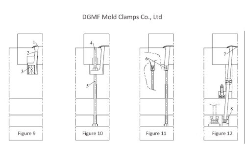
Figure 9 Structure of pitched roof
Figure 10 Structure of pitched roof
Figure 11 Structure of pitched roof
Figure 12 Structure of pitched roof
- Penetration surface
- Slanted top
- Mold spring
- Reset pin
- Eject the ejector rod
- Jack mounting groove
- The back of the buckle of the plastic part is an inclined surface
- The inclined groove of the inclined top seat
(5) In the structure shown in Fig. 13, a side ejection structure is installed on the side of the inclined top. When the plastic part needs to be cored on a large area side, it will inevitably cause the plastic part to be pulled and deformed when the inclined top is moved laterally.
Through this side ejection structure, the plastic part is effectively prevented from being pulled and deformed.
The working process of this structure is explained with the three different mold states shown in FIG. 13.
As shown in FIG. 13a, the state is not ejected at this time. The ejection pin on the inclined top is in the retracted state under the action of the spring force.
As shown in FIG. 13b, the state is the state in which the oblique top edge is pushed out and the side is pulled sideways. At this time, the back of the ejector pin on the inclined top is supported by the straight section of the mold core. Although the inclined top moves laterally, the ejector pin remains in a laterally immobile state to achieve the ejection of the plastic part from the inclined top. Avoid plastic molded parts being pulled and deformed.
As shown in FIG. 13c, at this time, the plastic molded part continues to be ejected by the inclined top, and the core is pulled out, and a hanging platform is provided on the back of the ejection pin, effectively realizing that the back of the ejection pin is not higher than the back of the inclined top.
Advantages: smart structure, can replace the slider structure, saving injection mold costs.
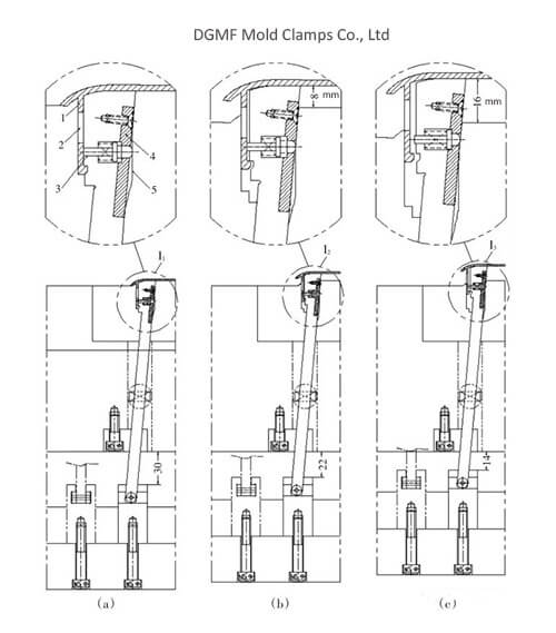
Figure 13 Slanted roof structure
- Plastic molded part
- Plastic molded part core hole
- Ejector pin
- Ejector pin pressing block
- Straight section of ejector pin guide groove
Conclusion
The various inclined ejection structures of the injection mold described above do not mean that these structures include all the inclined ejection structures. Various core pulling structures can be implemented in various forms. I hope you can apply them flexibly.
You may also be interested in the below articles:
Summary Of 50 Injection Mold Structure Operation Dynamic Diagrams