Structural Design Of Injection Mold For Concave Inner Shell
Through the structural analysis of the plastic injection molded parts of the internal undercut shell, determine the mold parting and demoulding scheme. The ejection scheme of the shell adopts the principle of the shrinking core, and the solution of using the second ejection plastic part.
In order to make the mold structure compact, the oil cylinder is introduced as the power unit of the Hough slider and the moving template ejecting the push plate, which enhances the reliability of the mold operation.
1. Introduction
In the product design process, some plastic shell parts with special external shapes (such as concave inner sides) are often encountered. Due to the particularity of their structural requirements, they bring great challenges to injection mold designers.
And at the same time, It is necessary to fully consider the feasibility of the plastic injection mold in the early stage of product structure design, and strive to meet the structural and functional requirements and at the same time maximize the design requirements of the mold, in order to achieve the best of both worlds.
The case described in this paper is the plastic injection demoulding principle of a concave inner shell on the periphery, focusing on the analysis of its shrinking core as a key component to participate in the entire moving process of demolding.
2. Shell process analysis
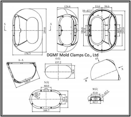
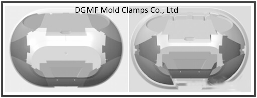
Figure 1 shows an engineering drawing of the technical requirements of the housing. It can be seen from Figure 1 that the basic shape is a sphere with an approximate track shape, and the inner periphery is provided with undercuts, so the demolding cannot be completed directly.
In addition, some structural features such as column holes and countersinks are also designed in the M, N, and O view directions of the shell. To solve the demolding problem of all these features, some special processing methods must be adopted to achieve it.
Through further analysis of the 3D modeling of the shell, the demoulding of the shell can be considered in two parts: first, the demolding of the shape, and second, the demolding of the inner concave.
In general, the basic idea of demoulding:
①Half slider implements shape demoulding;
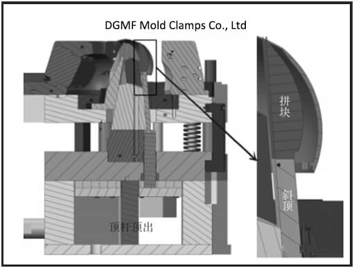
②Concrete core implements internal undercut demoulding in two steps, which is secondary ejection. In the first step, the movable template pops up the push plate, so that the inclined wedge fixed on the movable template and the push plate is displaced, so that the core generates an internal space so that the outer pieces of the core can shrink internally; the second step, the ejector bar The board is responsible for the final ejection of the shell through the inclined top.
Figure 1 Shell engineering drawing
3. Shell shape demoulding process
It is easier to make a judgment choice for the shape demoulding scheme of the shell. First of all, we must determine the location and direction of the parting line of the shape. As shown in Figure 2, if the fractal of the shape surface alone, the preliminary analysis of the scheme should have two kinds.
Obviously, the N-shaped runway-shaped large sink of the shell and the columns and holes attached to it need to be provided with an oblique slide block for demoulding.
Figure 2 Shell shape parting scheme
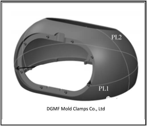
Option one, according to the PL1 upper and lower parting mode, the advantage is that the shell shape demoulding does not require a slider, but the parting position of the N-directional runway-shaped large sink is not at the maximum of its parting projection, resulting in its cavity being divided. It is obviously not feasible to form two acute angles of steel material at the die surface, which affect the die strength.
Option two, PL2 splits between the left and right sides, you need to set two Hough sliders, although there is also a runway-shaped hole in the “O direction” in Figure 1 of the shell, due to the optimization of the previous structural design, all glue positions are all on the core.
It does not matter whether the parting line of the Haff slider is located at the maximum side projection of this racetrack-shaped hole. The reason is that this racetrack-shaped hole does not require the slider to be demolded.
Based on the above analysis, the parting scheme of the shape part selects the Hough parting line PL2 of scheme two as the parting scheme and accordingly serves as the mold structure design of this case.
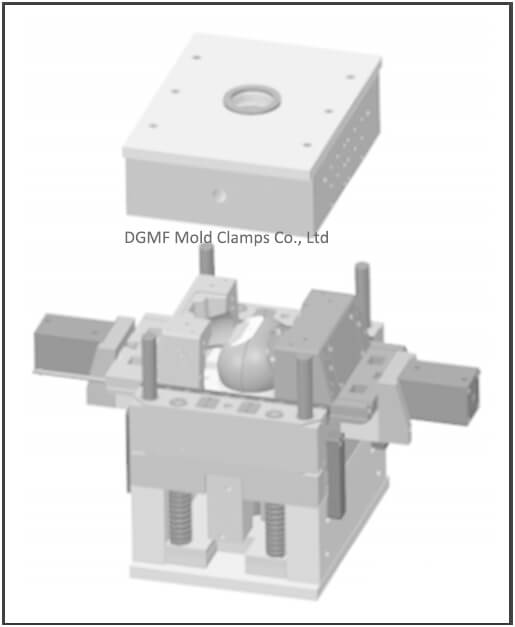
Figure 3 shows the case where the shell remains on the core of the fixed model after the moving and fixed models are opened. After the mold is opened, the two Haff sliders completely disengage the shell under the action of two oil cylinders.
Figure 3 Opening diagram of dynamic and fixed mode
4. Demoulding process of undercut inside the shell
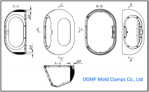
The inner concave demoulding inside the shell is actually the core of the problem to be elaborated in this case, so this part will be introduced in more detail. The distribution of obstacles around the inside of the shell is shown in Figure 4.
There are obstacles with ΔH unequal in value along most of the inside, making it impossible to demold directly according to the normal method. Therefore, it is necessary to formulate a set of feasible schemes for demolding the obstacles inside the casing.
The concave inside of the whole circle of the shell means that the entire outer ring part of the core responsible for molding must be retracted inward to achieve the purpose of demoulding. Therefore, the following design analysis is in principle.
It can be seen from FIG. 4 that the undercut obstacle inside the periphery of the housing with a racetrack-shaped opening accounts for more than 3/4. Because it is not possible to directly demold the interior of the housing, a mechanism for core shrinkage must be provided mission complete.
To achieve core shrinkage, a hollow position must first be created inside the mold during the molding process, so that the divided blocks of the peripheral core have enough space to shrink inwards, thereby completing the internal demolding of the shell.
For the convenience of description, circular core shrinkage is used as the shrinkage model for analysis. The step of disassembling the shrinkable core is decomposed into three steps as shown in FIG.
Figure 4 Distribution of concave obstacles inside the shell
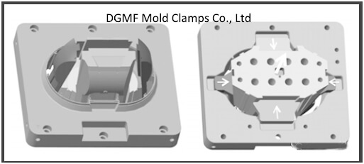
In Figure 5, the core is divided into the middle of the core is an independent part, the outer periphery is divided into 8 pieces, the dividing line is “eight”, and the 8 pieces are divided into two groups, The 4 pieces from 1 to 4 are spelled into the first group, and the 4 pieces from 5 to 8 are spelled into the second group.
The first step: the middle of the core is evacuated to make room for the 8 pieces; the second step: the first group of 1~4 4 pieces is retracted toward the middle; the third step: 1~4 pieces After sufficient space is produced by shrinking, the remaining peripheral second group of 4~8 pieces will shrink towards the middle. After 3 steps, the complete contraction of the entire core is completed.
Note: Is the space obtained after the shrinkage of the first group of 1~4 pieces sufficient for the shrinkage of the second group of 5~8 pieces? The strokes contracted in these two steps are generally 3mm larger than the internal obstacle value ΔH of the plastic parts, and the specific data calculation must be designed in advance.
Figure 5 Principle of shrinkable core
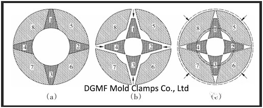
a — original state b — — the first group shrinks first c — — the second group shrinks later
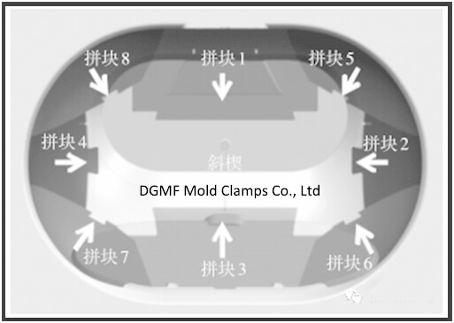
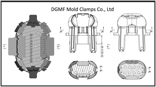
Based on this principle, the core of the case of this case is divided into the scheme shown in Fig. 6 correspondingly. The first group of tiles is 1~4, the second group of tiles is 5~8, and each of the two groups is divided by the shape of “eight”, the first group of tiles is the inner “eight”, the second group The block is the outer “eight” character, including the diagonal slant in the middle, and the entire core is split into 9 parts.
Figure 6 Shell core segmentation
In fact, the contraction of these two groups of pieces is contracted inward by the dovetail groove connected between them when the middle wedge is pulled away at the center position.
5. Introduction of the structure of the shrinkable core
As can be seen from Figure 7, Figure 8, and Figure 9, there are 8 groups of dovetail groove guide rails with different slopes on the center wedge.
When it is pulled away, it will leave an internal space for the first group and the second group to join together The block shrinks inward. Because the middle wedge is provided with a dovetail groove with a slope to match the first group and the second group of blocks, while the center wedge is pulled away, the first group and the second group of blocks will be driven inward by the dovetail groove Displacement, the core reaches the overall shape shrinkage.
Figure 7 core mechanism of shrink core
Figure 8 The inclined wedge and the first group and the second group of blocks
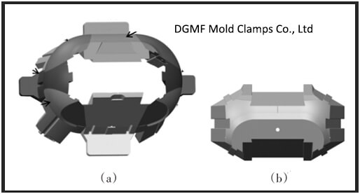
a is the outer two groups of pieces
b is the middle diagonal wedge
Figure 9 Comparison before and after center wedge extraction
Therefore, the drive division of inclined wedge and block is introduced first. As shown in Figure 10, the central wedge is fixed on the moving template, and the first group of blocks is fixed on the push plate and pushed by the wedge, the second group of blocks is used as a slanted top, first by the wedge After pushing, it is pushed out by the jack plate.
The pushing plate is pushed out by the oil cylinder provided on the moving template, so that the extraction action of the inclined wedge and the pushing plate can be realized, so that the first group retracts to the middle at the same time, as shown in FIG. 11.
Figure 10 The cylinder pushes out the push plate and the center wedge is pulled away
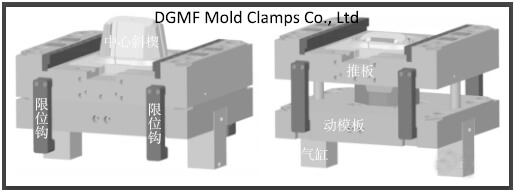
Figure 11 The first group of pieces shrinks
In fact, since the second group of tiles is also driven by the dovetail groove of the inclined wedge, when the first group of tiles is retracted, the second group of tiles is also retracted together.
At the same time, when the cylinder on the movable template pushes out the push plate, the push rod plate has a limit lever on the push plate, so that when the push plate is ejected, the push rod plate is also pulled out synchronously with it.
It is equivalent to the slanted top (the second group of pieces) is also pushed out the same distance. That is, the pulling action of the inclined wedge drives the adduction of the first group of blocks, and also the adduction of the second group of blocks, and at the same time, it also pulls the top plate, so that the top of the top plate is also synchronized the ejection action is shown in Figure 12.
Figure 12 Two groups of slanting tops
When the shrinkage of the first group and the second group of blocks is synchronized to the middle contraction process through the action of the slope guide dovetail groove of the middle wedge, the oil cylinder pushes the push plate until it is stopped by the four limit hooks.
At this point, the first contraction action of the patch group is completed. One key parameter to note here is that the skew angle of the first group of tiles is larger than the angle of the skew angle of the second group.
This prevents the two groups of tiles from simultaneously interfering when contracting. Increase the safety factor of the mechanical movement. After this first step of contraction is completed, the racetrack-shaped groove of the shell remains on the insert of the push plate and cannot be demolded, as shown in FIG. 13.
Therefore, it is necessary to push the ejector plate on the ejector of the injection molding machine to drive the inclined tops of the two groups of the blocks to make the final ejection, so that the shell is completely detached from the mold plate of the core. Complete the demoulding process of plastic parts, as shown in Figure 14.
Figure 13 The part of the shell that has not been demolded
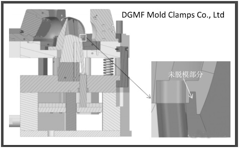
Figure 14 The shell is completely demolded
6. Motion analysis of key institutions
(1) The design principle of the oblique guide angle of core block.
It is necessary to deliberately design the slopes of the first group and the second group of blocks to different values.
The purpose of this is to make the two groups of blocks together when the inclined wedge is pulled away during the ejection of the push plate Differences in the relative distances drawn by contraction to the inside are different, forming gaps so that there is no interference between the two sets of tiles.
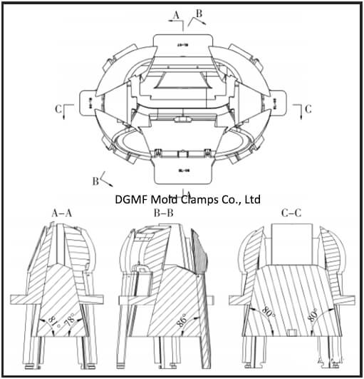
As shown in Figure 15, Figure 16.
The following calculations verify that, as shown in Figure 16, the 8 slopes that match the inclined wedge and the block are: block 1 is 12°, block 2 and block 3 are 10°, block 4 is 9°, Blocks 5-8 are all 4°. From the data, it can be concluded that all the slopes of the first group of 1~4 tiles are greater than 4° of the second group.
Assuming the extraction distance of the middle inclined wedge is 50 mm, the adduction distance of the first group of blocks 4 with the smallest oblique lead angle of 9° and the adduction distance of the second group of blocks can be calculated, and their sizes are compared.
Figure 15 Comparison and gap between the blocks before and after the slanting wedge extraction
a is before pumping off
b is after pumping off
c is block clearance after the wedge pumping off
Figure 16 Inclined dovetail slope
D=L • tanα (where D is the inner contraction distance; L is the wedge extraction distance; α is the oblique lead angle)
The adduction distance of block 4: D=50×tan9=7.9mm
The adduction distance of the second group of tiles: D=50×tan4=3.5mm
Obviously, the adduction distance of the first group of tiles is greater than that of the second group.
Because of the difference in the contraction distance, there is a gap when they move. Therefore, even if the two groups of blocks are retracted at the same time, they will not interfere even if they contract inward at the same time.
(2) Introduction of the design of the straight-top block plus the inclined top.
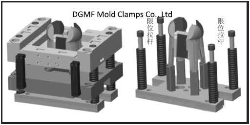
The second group of 5~8 pieces is inlaid on the inclined top rod, and at the same time, the inclined top rod and the straight top of the top rod plate are connected through a T-slot. Under the action of the injection molding machine, the inclined top ejection action is carried out, As shown in Figure 17.
Figure 17 Straight-topped and inclined-topped rods are connected with blocks
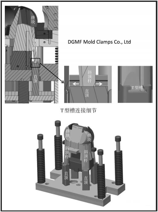
The second group of blocks adopts the advantages of the straight-top block connected to the inclined top rod through the T-shaped groove, which can effectively shorten the design length of the inclined top, without the need to configure a larger formwork for the top rod plate, saving costs.
At the same time, the rigidity of the inclined top can also be increased, so that the deformation of the inclined top is small, and the overall service life of the mold is effectively improved.
In summary, if this case is summarized, it is the evolution of a secondary ejection mechanism. The first time is that the push plate pushes out to drive the pieces to shrink inward, and the second time is that the pushrod plate drives the inclined top to push out the entire shell.
The principle of the shrinkable core mechanism introduced in this article is actually to split the core into the middle inclined wedge and the peripheral blocks, and the peripheral blocks are divided into two groups, and the “eight” shape is used to divide the blocks.
At the same time, the two sets of peripheral blocks and the middle inclined wedge are provided with a dovetail inclined guide groove to engage as a guide for contraction movement.
When the push plate on the movable template is pushed away, the inclined wedge fixed on the movable template will pull the outer two sets of pieces for internal contraction, thereby achieving the purpose of reducing the overall size of the entire core, making the inner side of the shell concave.
The obstacle body is smoothly separated from the core of the mold. Finally, the unmolded part of the casing is ejected by the inclined top mechanism on the ejector rod plate to complete the demolding work of the entire casing.
7. Conclusion
This case belongs to the typical injection mold design of a concave housing, and its significance lies in its certain expandability. It can provide the basic ideas of structure and mold design for the same type of plastic parts and has a certain reference role.
For the design method of the shrinkable core, we can also consider some discussion on the number of core divisions. Theoretically, the greater the number of lobes divided by the shrinkable core, the shorter the distance of the ejection stroke from shrinkage, which is of course an advantage.
However, when the number of lobes divided by the shrinkable core is too large, it will also increase the complexity of the core manufacturing. These situations must be considered comprehensively, and one side cannot be biased.
You may also be interested in the below articles:
Summary Of 50 Injection Mold Structure Operation Dynamic Diagrams