In recent years, with China’s large-scale infrastructure investment and the rapid progress of industrialization, the output and consumption of aluminum profiles in the whole industry have grown rapidly, and China has also become the world’s largest aluminum profile production base and consumer market.
After nearly 10 years of rapid growth, my country’s aluminum profile industry has entered a new stage of development and has shown many new development trends. And with the rapid development of construction, transportation, industry, automobile, solar energy, and LED industries, the requirements for high precision and high performance of aluminum alloy extrusion products are increasing day by day, and the cross-sectional shape of the profile is complicated and diversified.
There are many shortcomings in the design, so to get high-quality profiles, you must constantly learn, accumulate, constantly transform, and innovate in production and life. Mold design is an important link, so a systematic analysis of extrusion profile mold design is required. And gradually solve the problem through production practice.
Six Elements Of An Aluminum Extrusion Die Design
1.1 Dimensional analysis of aluminum extrusions
The size and deviation of the extruded parts are determined by the mold, extrusion equipment, and other related process factors. Among them, it is greatly affected by the change in the size of the mold, and the reasons for the change in the size of the mold are the elastic deformation of the mold, the temperature rise of the mold, the material of the mold, the manufacturing accuracy of the mold, and the wear of the mold.
1.1.1 Selection of tonnage of aluminum extrusion machine
The extrusion ratio is a numerical value indicating the difficulty of the die to achieve extrusion. Generally, the extrusion ratio is applicable between 10 and 150. If the extrusion ratio is less than 10, the mechanical properties of the product are low;
Otherwise, if the extrusion ratio is too high, the product is prone to defects such as rough surface or angle deviation. Solid profiles are often recommended for extrusion ratios around 30 and hollow profiles around 45.
1.1.2 Determination of overall dimensions
The external dimensions of the extrusion die to refer to the outer diameter and thickness of the die. The external dimensions of the mold are determined by the size, weight, and strength of the profile section.
1.2 Reasonable calculation of extrusion die size
When calculating the die hole size, the chemical composition of the extruded aluminum alloy, the shape of the product, the nominal size and its allowable tolerance, the extrusion temperature, and the linear expansion coefficient of the mold material and the extruded alloy at this temperature, the product cross-section is mainly considered The characteristics of the geometric shape and its changes during stretching and straightening, the size of the extrusion force and the elastic deformation of the die and other factors.
For profiles with large wall thickness differences, the thin-walled parts and sharp edge areas that are difficult to form should be properly enlarged.
For the die holes of flat, wide, and thin-wall profiles and wall profiles with large width-to-thickness ratios, the size of the truss section can be designed according to the general profile, and the size of the web thickness, in addition to considering the factors listed in the formula, need to consider the mold elastic deformation and plastic deformation and overall bending, the distance from the center of the extrusion cylinder and other factors.
In addition, the extrusion speed and the presence or absence of a traction device also have a certain effect on the die hole size.
1.3 Reasonable adjustment of metal flow speed
The so-called reasonable adjustment is to ensure that every particle on the cross-section of the product should flow out of the die hole at the same speed under ideal conditions.
As far as possible, use a porous symmetrical arrangement. According to the shape of the profile, the difference in wall thickness of each part and the difference in specific circumference, and the distance from the center of the extrusion barrel, design sizing belts of unequal length.
Generally speaking, the thinner the wall thickness somewhere in the profile, the greater the perimeter, the more complicated the shape, and the farther away from the center of the extrusion barrel, the shorter the sizing zone.
When it is still difficult to control the flow rate with a sizing belt, the shape is particularly complicated, the wall thickness is very thin, and the part far away from the center can use a flow angle or a material guide cone to accelerate the metal flow.
On the contrary, for those parts with much larger wall thickness or very close to the center of the extrusion cylinder, the obstruction angle should be used to supplement the obstruction to slow down the flow velocity here. In addition, you can also use process balance holes, process margins, or use anterior chamber mold, diversion mold, change the number, size, shape, and position of the distribution hole to adjust the metal flow rate.
1.4 Ensure sufficient mold strength
Since the working conditions of the mold during extrusion are very bad, the strength of the mold is a very important issue in the design of the mold. In addition to rationally arranging the positions of the die holes, selecting appropriate die materials, and designing a reasonable die structure and shape, it is also very important to accurately calculate the squeezing force and check the allowable strength of each dangerous section.
At present, there are many formulas for calculating the extrusion force, but the modified Berrin formula still has engineering value. The upper limit solution of the squeezing force also has a good applicable value. It is relatively simple to calculate the squeezing force using the empirical coefficient method.
As for the mold strength check, it should be done separately according to the type of product, mold structure, etc.
Generally, the flat mold only needs to check the shear strength and bending strength. The tongue die and plane split die need to check the shear, bending, and compressive strength, and the tongue and needle tip also need to consider the tensile strength.
An important basic problem in strength checking is to choose the appropriate strength theoretical formula and more accurate allowable stress. In recent years, the finite element method can be used to analyze the stress and check the strength of, particularly complex molds.
1.5 Working belt width
Determining the working band of the split mold is much more complicated than determining the half-mold working band. Not only must the wall thickness difference of the profile, the distance from the center be considered, but also the situation that the die hole is covered by the split bridge must be considered.
The die hole under the shunt bridge has to be considered thinner due to difficulties in metal flow. When determining the working band, first find out the thinnest wall thickness of the profile under the shunt bridge, that is, the place with the largest metal flow resistance.
The minimum working band here is set to twice the wall thickness. The thicker wall or metal is easy to reach Where the working belt needs to be properly considered for thickening, generally according to a certain proportional relationship, plus the flowable correction value.
1.6 Mold hole empty knife structure
The empty knife of the die hole is a structure supported by the cantilever at the exit end of the die hole working belt. When the wall thickness of the profile is t ≥ 2.0mm, a straight empty knife structure that is easy to process can be used; when t <2mm or an inclined empty knife can be used at the place with a cantilever.
Common problems and examples in mold design
2.1 The role of secondary welding chamber
Extrusion dies to play a vital role in the production of aluminum profiles and directly affects the quality of the extruded products. However, in actual production, the design of the extrusion die depends more on the designer’s experience, and the quality of the die design is difficult to guarantee, requiring multiple trials and repairs.
According to the insufficiency of mold design, an optimized design plan for opening a secondary welding chamber in the lower mold was proposed to make up for the defect of insufficient feeding in the mold processing and to avoid the defects of opening, closing, and uneven shape before and after the output caused by insufficient feeding
And effectively solve the problem of uneven speed distribution in the design. Therefore, in the optimization scheme, the temperature distribution and stress distribution on the section of the profile is more uniform, which greatly improves the output.
The mold design is shown in Figure 1:
Figure 1: Design drawing of the secondary welding chamber
2.2 The role of secondary diversion
In the design of extrusion dies, for solid profiles with large wall thickness differences, two-stage diversion.
Example
The initial mold design is composed of ordinary molds and mold pads. The design is shown in Figure 2.
The first time the machine is used, it is very unsatisfactory, the angle is small, and the thin-walled part is ultra-thin and ultra-small.
Even if the mold is repaired, the thin-walled part is enlarged and the working belt is lowered, which is still not ideal. Aiming at the shortcomings of the initial mold design, the second time using the deflector design, it is proposed to set up a second-level diversion optimization design scheme in the mold, which effectively solves the problem of uneven speed distribution in the initial mold design.
Specifically, through the direct diversion of the thin-walled part, the thick-walled part spreads 30 degrees at the discharge port, and the size of the thick-walled part’s die hole is slightly increased, and the die hole size is opened at a 90-degree angle to 91 degrees. The sizing work belt has also been modified appropriately.
The design is shown in Figure 3, Model 2 is basically qualified for the first time.
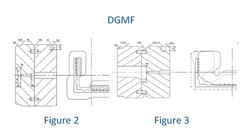
Design drawing of secondary flow guide for aluminum extrusion die
Summary
After continuous learning and accumulation, constantly inquiring about related mold design information, through renovation and innovation to optimize mold design, and through production, practice to verify success.
- 1 The working belt of the extrusion die is to control the metal flow and stabilize the product size and surface quality.
- 2 determining principles
- The minimum length of A should ensure the stable cross-sectional size of extruded aluminum products and have sufficient wear resistance.
- The maximum length of B should be determined according to the maximum effective contact length between the metal and the working belt during extrusion.
- For angular, T-shaped, trough-shaped, and I-shaped, the working band can be the same except for the working bands that are shortened by three-sided friction resistance at each end, such as the die holes on concentric circles.
- For aluminum profiles with complex D cross-sectional shapes and unequal wall thicknesses, it is necessary to design working belts of the unequal length according to the wall thickness and adopt a slant transition at the disparity of change to avoid ribbing in the manufacturing process.
In this paper, through systematic analysis of aluminum profile extrusion die design, find out the rules of aluminum alloy profile die design, rationally arrange to die holes, increase balance die holes, and combine actual production to solve the two major problems of metal flow unevenness and die strength.
Extrusion of products whose cross-sectional geometry meets the requirements of users.
The practice has proved that the design of the extrusion die structure is reasonable to obtain the first inspection and long life because only through systematic analysis of the designed extrusion die drawing can it be determined Whether its performance meets the design requirements.
In addition, according to the problems often encountered in mold design, the effects of secondary welding and secondary flow are summarized.
You may also be interested in the below articles:
Summary Of 50 Injection Mold Structure Operation Dynamic Diagrams