One-die Double-punch Compound Die Technology Sharing
The structure exploration and manufacturing process analysis of the one-die double-punch compound die. Through the systematic optimization of the structure and the analysis of the manufacturing process, the die structure was innovated and the technical difficulties of the one-die double-punch compound die were solved.
The punching quality of the punching sheet meets the design dimensional accuracy requirements, and the mold structure meets the user’s requirements.
In the stamping production process, ensuring a low scrap rate is one of the most important technical indicators of modern stamping production. In stamping production, the material consumption cost of stamping parts can reach 60%-75% of the total cost. For every 1% reduction in stamping waste, the cost will be reduced by 0.4%-0.5%.
Reasonable use of materials is an effective measure to reduce costs. Especially in batches and mass production, the annual output of stamping parts reaches hundreds of thousands of parts or even millions of parts. The economic effect of the reasonable use of materials is more prominent.
Analysis of workpiece structure and blanking process
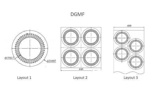
As shown in Fig. 1 for a certain type of motor stator, the punching material is silicon steel; the material thickness is 0.35mm. The stator punches have 48 uniformly distributed grooves, and the punching burrs are required to be less than 0.02mm and the surface is smooth.
Punching process analysis: the production volume of punching tablets is large, and the design scheme of double punching with tape and one die is used for punching to improve production efficiency.
Selection of nesting method is using the nesting method of Figure 2, the utilization rate of raw materials is about 32%; using the nesting method of Figure 3, the utilization rate of materials is about 39%, which effectively improves the utilization rate of raw materials, Reduced production costs.
Punching mold structure design
Figure 4 shows the punch mold structure. The punching piece is punched with 400mm strip material as shown in Figure 3. If the parts are pushed out with the scrap during the punching process, the stator punching piece is pushed out with the strip material.
When a certain safe distance is pushed out, the operator needs to sort out the stator Punching and scrap, the stator has many punching grooves, and the punching material (thickness 0.35mm) is thin, and the sorting difficulty is relatively large.
Moreover, this punching scrap needs to be set to the rotor punching, and the scrap cannot appear during sorting If it is deformed, secondary punching cannot be performed, which causes waste of raw materials. The die adopts one die and two punches. The speed and difficulty of sorting are significantly increased, which seriously restricts the production efficiency and affects the production cycle.
Therefore, the die adopts the way of leaking material, and the stator punching piece adopts automatic material feeding, which is simple and convenient to operate, does not need to sort waste materials, saves manpower, and the waste materials will not be deformed.
The thickness of the stator punching material is 0.35mm silicon steel sheet. According to experience, the die gap is 0.02~0.04mm, which is a small gap punching. The die guide system uses a ball guide system to ensure high accuracy of service life.
During the punching process, to avoid the influence of punching presses and other factors on the die gap, the guide system keeps the guide pin and guide bushing from separating during the entire punching process.
Remarks: Figure 4 Punch mold structure diagram
- Upper die base
- The guiding system I
- Upper fixing plate
- Unloading screw
- Pushing plate
- Convex mold
- Playing plate
- Concave mold
- Guiding system
- Stopper pin
- Mold Spring
- Unloading Material plate
- Lower pad
- Convex and concave mold
- Lower mold base
The manufacturing process of the main parts of the mold
The calculation formula of die punching force:
F punch =1.3Ltτ=1.3×3402.94×0.35×560=86.7t
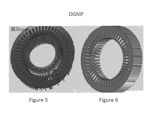
Using the software to simulate the stress in the punching process of the male and female molds, the deformation of the force is shown in Figure 5.
The degree of waste accumulation in the male and female mold cavity will seriously affect the accuracy and strength of the male and female molds, especially for thin-walled parts.
If the material is not smooth, the waste material will accumulate in the cavity of the convex and concave model, which will easily cause the deformation of the convex and concave mold, so that the gap between the mold is uneven, the punching burr becomes larger, the workpiece does not meet the technical requirements, and the edge of the convex and concave mold may also be pulled;
The accumulation of waste materials to a certain degree will make the convex and concave molds crack and the molds cannot be used normally. Therefore, a reasonable leakage structure has a great influence on the accuracy and life of the molds.
The structure of the optimized male and female molds is shown in Figure 6.
The inner cavity adopts 8’oblique cutting edges along the circumference, the effective thickness of the cutting edges is 12mm, and the rest adopts the structure of a single side expansion of 0.2mm to ensure the strength of the male and female molds. Under the premise of achieving smooth leakage.
The key parts of the mold (convex die, concave die, convex-concave die, etc.) are all made of Cr12Mo1V1 with good wear resistance and hardenability, mainly through quenching (hardness of 58~62HRC), tempering, cryogenic treatment (elimination of internal stress in the material) heat treatment process.
Its main manufacturing process, roughing before heat treatment, each hole (except pinhole) processing meets the requirements of the drawings, 1.5mm roughing is left on each side of each cavity, to reduce stress and deformation during the finishing process, full type slow wire after finishing machining, the craft table keeps its shape, and the coordinate grinding corrects the craft table.
For the concave die and the convex die, they can be combined into one spare material to save raw materials. The amount of reserve before finishing is separated. The finishing of the punch takes into account the press-fitting problem. It is divided into two clamping processes, and both are based on the two pinholes. At the splice, the fitter repairs the oil and connects it.
The upper and lower mold bases of the mold are made of the Q235A sheet. Except for the proper finishing grinding amount of the guide column guide sleeve hole, type hole, and plane on the workpiece, the rest is processed in place.
Flat grinding and flatness are ensured during finishing, and then the guide column and guide bush holes are machined on the CNC machine to achieve hole pitch position accuracy within ±0.03mm.
The lower die base is over-matched with the bushing of the guide system; due to the guide bush, The anaerobic adhesive is used to fix the upper mold base.
Considering the processing accuracy and operability, the clearance of the joint is guaranteed to be 0.1~0.12mm on one side. Before bonding, the grease must be cleaned with acetone and then glued;
The processing and manufacturing of the unloading plate and the pushing plate are divided into three stages of roughing and finishing:
① roughing mainly removes the part of the remaining part of the forming part on the workpiece, leaving an appropriate subsequent processing allowance;
② roughing After heat treatment and tempering, it is necessary to improve the toughness and strength of the part and reduce the amount of quenching deformation afterward;
③The heat treatment aging is required before finishing, to eliminate the brittleness and internal stress of the part after quenching, and the precision machining is on a precision surface grinder Grind two planes, the parallelism is controlled within 0.01mm, and the discharge plate and push plate are processed by wire cutting to meet the relevant technical requirements.
In addition, considering that the single punching force of the die is about 83.7t, the punching force of one die and two punches reaches 160t. When punching, the lower die holder needs to bear a large punching force; The lower die base is hollow, and the possibility of deformation is very large, which affects the accuracy of the mold.
Therefore, the lower backing plate is made of 45 steel. After roughing, it is quenched to 43~48HRC. After finishing, the thickness is required to be more than 45mm to compensate for the lower die base. Deformation defects during punching.
Punch mold assembly
The die belongs to one die and two punches, and the relative position of the two-cavity of the die needs to be ensured. Therefore, the concave model cavity adopts the overall structure, and the accuracy of the cavity position is guaranteed by the finished slow wire; when the assembly is reversed, the die and the fixed plate are the first.
The upper mold base is assembled together, evenly pad 0.02mm gap paper in the concave mold cavity, assemble the lower mold body (convex and concave mold, lower backing plate, lower mold base), split mold, the inner cavity of convex and concave mold evenly pad 0.02mm gap paper Assemble the punch and fix it with screws.
After assembling, the punch and die are evenly filled with gap paper to ensure the uniformity of the gap between the parts. If the gap is not uniform, you can continue to adjust the convex and concave mold, repair the oil line cut to ensure the uniformity of the gap. Then fix it with pins to ensure the stability of the position.
Conclusion
After exploring the structure of a one-die double-punch die, after trial production, the trial die was successful at one time. The punched parts had small burrs and a flat surface, saving raw materials and solving the technical problem of the difficulty of multiple leaks in the groove shape.
Moreover, the flatness of the blanks during the secondary punching of the waste material has also been solved, which meets the technology of the parts and the requirements of the company for mass production.
You may also be interested in the below articles:
Summary Of 50 Injection Mold Structure Operation Dynamic Diagrams