In the production process of stamping parts, the main problems that affect the production pass rate are high points and pits, which directly cause the rework of the parts, increasing labor and energy consumption costs.
How To Solve The Iron Filings Produced By Stamping Die?
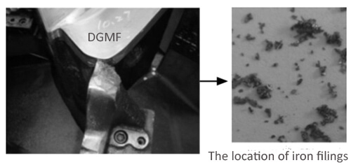
The location of iron filings
Through the on-site confirmation of the on-site production process, it was found that there was a large number of iron chips in the cutting edge of the mold and the scrap shearing part of the second process. After sampling and comparing the shape of the iron chips that caused the high point, it was found that they were basically the same.
Therefore, it is determined that the iron scraps that cause the high point of the workpiece come from the shearing part of the mold sheet material in the second process, as shown in FIG. 1.
Causes of iron filings entering the mold
As the upper mold of the mold moves upward, the air pressure inside the mold drops, and the air becomes thinner, forming a negative pressure area. Due to the difference in air pressure, the outside air flows into the mold, and the airflow will suck the iron chips generated from the shearing part of the sheet into the mold.
Inside the cavity, the mold cavity profile is contaminated. The faster the upper die moves, the faster the negative pressure is formed, and the stronger the pressure, the faster the airflow. Due to the increase in production efficiency, the movement speed of the upper mold increases accordingly, the negative pressure cannot be reduced or avoided.
Iron filings and solutions
3.1 Mechanism analysis of sheet shearing process
The sheet shearing process is divided into 3 stages
Elastic deformation stage
the punch squeezes the sheet to cause local elastic stretching and bending deformation.
Plastic deformation stage
In the plastic deformation stage, when the stress in the deformation zone of the sheet material satisfies the yield condition, plastic deformation is formed, the material is squeezed into the die, and the cold deformation is strengthened.
Fracture separation stage
In the fracture separation stage, as the edges of the convex and concave die continue to be pressed in, the upper and lower cracks extend so that when they meet and overlap, the sheets are separated.
The cross-section obtained after the sheet is sheared is not smooth and vertical, but four characteristic areas are formed on the cross-section, as shown in Figure 2.
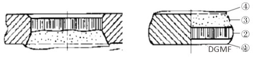
Figure 2 Shear section
①Cracked area
Due to the gap between the punch and the die, the material exerts a pulling effect on the material during plastic flow, and the material on the side of the cutting edge forms a rounded corner due to the greater tensile stress. The better the plasticity of the material and the greater the gap between the punch and the die, the greater the collapse angle.
②Bright band
The very smooth surface formed by plastic deformation of the material is the most ideal blanking section. The better the plasticity of the material, the delayed cracks will be delayed, and the brighter the band will be. In addition, factors such as the gap between the punch and the die and the degree of wear of the cutting edge have a greater influence on the size and distribution of the bright band.
③Fracture zone
A torn surface with a very rough surface formed by the main crack penetration surface. When the plasticity of the material is good, the bright zone is wider, and the width of the fracture zone is reduced accordingly.
④ Burr
Burr is naturally formed due to the crack on the side of the edge. The burr affects the appearance, feel, and performance of the punched part, and forms iron filings after shedding.
Therefore, the four characteristic regions formed on the cross-section of the sheet after shearing have the following characteristics:
① the better the plasticity of the material, the greater the gap between the punch and the female die, the greater the collapse angle;
② the better the plasticity of the material, Cracks will be delayed, and the brighter band will be wider;
③ The gap between the punch and the female die and the degree of wear of the cutting edge has a greater impact on the size and distribution of the bright band.
3.2 Quality improvement of sheet shearing parts
In order to improve the cutting quality and reduce the occurrence of sheet metal scrap, we will prevent and improve the gap between the punch and the die, the degree of edge wear, and the gap between the scrap knife and the punch.
3.2.1 Gap and die gap control
(1) The cutting edge gap is unreasonable. The theoretical value of the theoretical gap should be 5%~8% of the material thickness, the material thickness of the stamping outer plate is 0.7mm, and the gap should be 0.035~0.056mm.
- Large gap: The cracks generated at the top and bottom of the material do not coincide, and the tensile stress in the material will increase, causing a tensile fracture to occur prematurely so that the plastic deformation ends earlier, the bright band is narrow, and the fracture zone and rounded zone are widened. The burr is large and the cross-section quality of the blank is poor.
- The gap is small: the material between the upper and lower cracks will be sheared a second time as punching progresses, forming a second bright band on the cross-section, and there is a residual broken band in the middle of the bright band. If the gap between the punch and punch is too large or too small, iron filings will be formed.
Control method
① Take out the material core of the trimming die, put the die on the grinding machine, apply the red powder to the punch, enter the closing parameters used in production, check the coloring of the cutting edge of the concave die;
② measure the gap between the concave and convex die with a feeler gauge.
(2) The gap between the punch and the die is not uniform, resulting in a bad shape of the part, and the mismatch between the part and the mold surface results in an uneven force on the cutting edge during work, and the part is deformed greatly under stress. Iron filings are produced; at the same time, there may be off-position cutting and iron filings.
Control method
①Apply red powder in the second process, and check the coloring of the pressing core on the research machine;
②Apply red powder in the first process, and check the coloring with the punch and scrap knife.
3.2.2 Cutting edge wear degree control
It is mainly controlled from four aspects, namely, the verticality of the cutting edge, the amount of cutting edge intake, the cutting edge hardness, and the cutting edge smoothness.
The verticality of the cutting edge. When the cutting edge is tapered, the cutting edge is linear contact rather than surface contact, which is very easy to wear. After repeated punching, the cutting edge wear increases and the gap is uneven, which leads to iron scraps in the later trimming.
When the cutting edge is tapered, due to deformation, the zone belongs to the combined deformation of shearing, stretching, bending, and squeezing, and the excess material is sheared upwards by scrap and die edges to form chips.
When the blanking gap is very small, burrs are formed, which are easy to fall and produce iron chips; at the same time, a negative gap occurs, which generates lateral force to squeeze the cutting edge, and the unevenness of the gap occurs after the wear of the cutting edge is increased, and iron chips are also easy to produce.
Control method: Apply the red powder on the side of the vertical knife, slide along the cutting edge, and check the coloring.
(2) The amount of ingestion at the cutting edge. The trimming contour of the outer plate is longer and has a somewhat complicated shape, which requires very high verticality of the cutting edge. If the verticality of the cutting edge is improper, excessive punching will cause secondary extrusion of the cross-section, and finally, the burr will be extruded and bonded At the head of the blade, iron filings are formed.
Control method
The depth of ingestion is controlled at 2~3mm, and the amount of ingestion of the cutting edge is determined according to the wear marks of the cutting edge.
(3) Cutting edge hardness. The insufficient hardness of the cutting edge reflects that the cutting edge becomes blunt and rounded, which leads to continuous trimming, burr, and squeeze iron filings.
Control method
The hardness of the edge after quenching is required to be 55~65HRC. Use a hardness tester to measure and record the strength of the edge.
3.2.3 Blade finish control
The poor finish of the cutting edge working surface affects the quality of the cross-section of the workpiece. The cutting edge working surface rubs against the workpiece. After the top dead center, the workpiece is pulled down, and after the bottom dead center, the workpiece is brought up, resulting in trimming tape or iron filings produce.
Control method
The blade finish requires Ra0.8~1.6μm, and the roughness tester is used to detect the mold edge finish.
Typical case analysis
Case 1
For the scrap cutting punch on the trimming line, triangle chips are most likely to occur. Solution: After the tip of the cutting punch is in contact with the sheet, the sheet is first punctured to avoid tearing debris, and then the two edges of the waste punch are cut like two scissors.
To reduce the tearing of the sheet by the waste punch, thus avoiding the generation of triangular tearing debris. The main point of the tip of the punch is to ensure that the cutting edge is sharp and sharp, and the gap cannot be too small to prevent chipping.
Case 2
The main reason for the generation of strip-shaped debris is that the upper punch punctures the sheet, and the edge of the scrap is larger than the end face of the lower die scrap punch. The scrap punch cuts off the excess sheet (secondary shear), resulting in debris. The debris is brought into the mold to create the impression.
Solution
According to the length of this batch, use the lower punch to make a knife to eliminate the secondary shear and solve the cutting edge debris. It is forbidden to polish the tip of the waste punch, and at the same time, it should be tested by the press of the press to confirm the status.
Conclusion
Through the research of this project, the problem of the control method of the iron chips generated by the stamping die is standardized by the strongly related factors.
The gap between the edge of the convex and concave die is 5%~8% of the material thickness; the hardness of the die edge requires 56~65HRC;
The roughness value of the edge Requires Ra0.8~1.6μm; the depth of the cutting edge requires 2~3mm; the gap between the scrap knife and the punch requires 0.5~1.0mm; the demagnetization cycle of the scrap knife requires at least 1 time/year.
Through the standardization of strongly related factors, we have a clear understanding of the causes of iron chips produced by stamping dies, master the specific control methods for controlling the generation of iron chips, and have important reference points for mold maintenance standards and early acceptance control points.
You may also be interested in the below articles:
Summary Of 50 Injection Mold Structure Operation Dynamic Diagrams