This article introduces the comparison of the mold structure of plastic injection molds with different concave moldings. The inner cavity core pulling adopts the form of lateral molding with inclined guide slide rods to simplify the ejection of the plastic molded parts after molding and improve the injection mold, production efficiency, and degree of automation.
How To Design An Injection Mold For Plastic Cover?
Introduction
Plastic molded parts with concave and convex sides are formed on the side, or parts with internal and external threads formed with general precision are processed. The ejection and demoulding mechanism for plastic parts in injection molding generally adopts a movable core designed for manual demolding outside the machine.
Or adopt the side parting mechanism such as inclined guide column slider or inclined guide slide bar in the injection mold structure to realize the method of automatic ejection and demoulding.
In order to simplify the mold structure, and at the same time ensure the molding quality of the plastic parts and facilitate the demolding after injection molding, the side parting form of the corresponding structure should be correctly selected.
In order to ensure that when the plastic part is demolded after injection molding, the molding cavity part in the lateral parting member is separated from the plastic part in advance, leaving space for the plastic part to be demolded.
Injection molding processability analysis of plastic parts
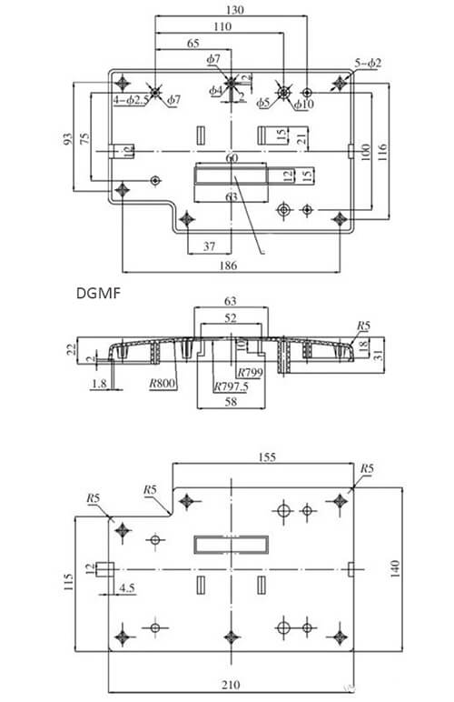
The structure graphics and related dimensions of the plastic parts of the decorative surface are shown in Figure 1. The material used is ABS.
2.1 Plastic injection molding characteristics
ABS is an engineering plastic widely used in home appliance housings, various structural parts, connectors, decorative parts, etc. It has a moderate melt index and has good melt fluidity and moldability during injection molding.
2.2 The structural manufacturability of plastic molded parts
(1) Analysis of dimensional accuracy and structural characteristics of plastic molded parts.
The plastic molded part is a rectangular arc-shaped shell. On both sides of the shell, there is a symmetrical 1.8mm convex shoulder for assembly. In the middle, there is a symmetrical 52mm convex and concave-convex shoulder for mounting other structural parts.
The five corners of the bottom of the plastic molded part have five small cylinders with a diameter of φ 2mm, which are used for fixing during assembly. There are also 4 small cylinders (2.5 mm hole in the middle) at the rear of the cover. In the middle of the curved surface cover, a rectangular enterprise labeling window of 15×63mm is also opened.
(2) Surface quality analysis of plastic molded parts.
The plastic molded parts are the exterior cover after the whole assembly. The curved surface is required to be smooth and round, and the curved shape must not have gate marks. Others have no higher roughness requirements.
(3) Technical analysis of the structure of plastic molded parts.
The shape of the plastic molded part is a rectangular arc surface shell, and the wall thickness is relatively uniform (about 2.8mm), which meets the requirements of injection molding.
Design of parting surface and pouring system
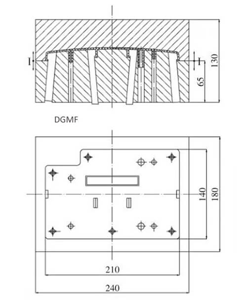
(1) Selection of the parting surface.
When selecting the parting surface, according to the selection principle of the parting surface, the maximum contour of the plastic molded part should be used as the moving and fixed parting interface.
At the same time, it is conducive to the exhaust of the mold cavity, and the plastic part moving the injection mold part is kept as much as possible. In the design of this injection mold, the rectangular arc is the largest contour of the plastic part. Therefore, this place is selected as the horizontal parting surface between the moving and fixed molds, as shown in Figure 2.
(2) Design of pouring system.
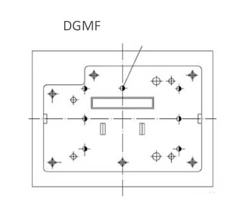
Because the plastic part is an external-facing cover, the curved surface is required to be smooth and round, and the shape of the curved surface must not leave gate marks.
Therefore, when designing the pouring system, a 15×63mm rectangular window is opened in the middle of the curved surface cover, and a side gate is opened. In injection molding, the process of filling the material flow and the flow of the pouring system is long, but the feeding port of the pouring system is opened at both ends of the 63mm rectangular window.
The size of the pouring runner is shortened so that the melt is quickly filled in the mold, and the molding quality of the plastic part is not affected due to poor welding. After the gate is removed, an enterprise label is affixed to the window to ensure the appearance requirements of the plastic molded parts, as shown in Figure 3.

Injection mold cavity design
(1) The outer contour of the decorative cover is the largest contour of the plastic part.
Therefore, this place is selected as the horizontal parting between moving and fixed molds.
To simplify the structure of the mold cavity. Module combination interfaces with horizontal arc type as a dynamic and fixed mode. The large-sized inserts for processing the overall structure are inserted into the moving and fixed templates respectively, as shown in Figure 4.
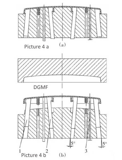
Remarks:
Figure 4 After the injection molding, when the plastic part is pushed out, the slide bar moves outward or inward to make the plastic part demold smoothly.
a is the fixed mold moves up after injection molding, the plastic parts have not been launched yet
b is the plastic part is completely pushed out of the moving mold part
- The sliding guide rod pushes the plastic part while moving inward
- The sliding guide rod moves outward while pushing the plastic parts
- Round auxiliary push rod
(2) The design of the forming cavity of the side core pulling part.
Because there is a symmetrical 1.8mm internal convex shoulder on both sides of the housing, there is a symmetrical 52mm convex and concave shoulder on the middle part for mounting other structural parts. The two molded parts of the plastic parts must adopt the lateral parting structure, that is, the 1.8mm inner convex shoulders on the two sides of the molded shell, and the inclined guide slide bar is used for molding at this place.
At the end of the injection, while pushing out the plastic part, the oblique sliding guide rod moves inward to disengage from the plastic part, and the mounting shoulders with an outer convex and concave interval of 52 mm in the middle part use the oblique guide sliding rod.
At the end of injection molding, while pushing out the plastic part, the oblique sliding guide rod moves outwards and disengages from the plastic part. As shown in FIG. 4, FIG. 4a shows that after injection molding, the fixed mold moves up and the plastic part is in a state where it has not been demolded. Figure 4b shows that after injection molding, the fixed mold moves up and the plastic part is completely pushed out of the moving mold part.
(3) Confirmation of the launching organization.
For the structural characteristics of the plastic parts although the thickness is relatively uniform (2.8mm). In order to prevent the post-deformation of the plastic parts during the ejection process after molding, when determining the mold assembly structure scheme, the design scheme of the ejection mechanism must adopt the demoulding form pushed out by the inclined guide slide bar and the auxiliary push rod, as shown in Figure 5.
Injection mold structure design
The assembly structure of the mold is shown in Figure 6. In order to ensure the molding accuracy of the mold and prevent the post-deformation of the plastic part due to the unreasonable molding method, the plastic part chose the form of the inclined guide slide bar plus two sets of auxiliary pushrods.
The selection of the inclination angle of the two sets of inclined guide slide bars should be reasonably determined according to the size requirements of the demoulding movement. That is, the horizontal moving distance dimension S = the actually required dimension of concave or convex B + the safety dimension L required for the movement of the plastic part during the ejection process after demoulding.
The inclination angle of the inclined sliding guide bar is generally 5° to 8° as the best. When the inclination is too large when the plastic part is pushed away from the mold, the friction torque between the oblique sliding guide rod and the mold cavity is large, which tends to increase the wear of the oblique sliding guide rod.
However, when the slope is too small, the plastic part cannot be demolded due to damage caused by the horizontal distance dimension S moving too small during the process of pushing the mold away from the mold.
Remarks: Fig. 6 Die assembly structure diagram
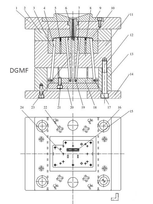
- Fixed mold seat plate
- Fixed template
- Moving mold forming insert
- Oblique sliding guide rod
- Round core
- Sprue Bushing
- The oblique sliding guide rod
- Round core
- Locating ring
- Fixed mold forming insert
- Moving template 12,
- Hexagon Screw
- Spacer
- Movable mold base plate
- The movable mold inserts
- Mould frame guide bushing
17&19. Sliding guide slide Column pin
- Pushrod fixing plate
- Pushrod pad
- Reset lever
- Z-shaped feed rod
- Round push rod
In particular, it should be pointed out here that the design slope angles of the two sets of inclined slide guides (pieces 4 and 7 respectively) of this mold should be exactly the same, otherwise the mold will not work properly, as shown in Figure 4b.
You may also be interested in the below articles:
Summary Of 50 Injection Mold Structure Operation Dynamic Diagrams